5052 H32 Aluminum size and thickness options

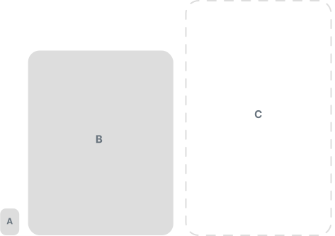
Cut Sizes

  • A..25" x .375"minInstant Pricing
  • B.30" x 44"maxInstant Pricing
  • C.44" x 56"maxCustom Quote

​​​​​​Thicknesses

Laser cut, +/- .005" tolerance

  • .040" 1.02mm
  • .063" 1.60mm
  • .080" 2.03mm
  • .090" 2.29mm
  • .100" 2.54mm
  • .125" 3.18mm
  • .187" 4.75mm
  • .250" 6.35mm
  • .313" 8.00mm
  • .375" 9.53mm
  • .500" 12.7mm

5052 H32 Aluminum material details and specifications

.040"1.02mm 5052 H32 Aluminum

Material Details & Specifications

5052 .040" GENERAL DETAILS
Advertised Thickness 0.040" (1.02mm)
Gauge 18
Thickness tolerance positive 0.004"
Thickness tolerance negative 0.004"
Mill Finish Cold Rolled
Top/Bottom finish Identical both sides
Sourced from Global
LASER CUTTING SPECIFICATIONS
Cutting process Fiber laser
Cut tolerance +/- 0.005"
Flatness tolerance before cutting +/-0.030 per foot
Min part size .25″ x .375″
Max part size 44″ x 30″
Min hole size .015″
Min bridge size .020″
Min hole to edge distance .020″
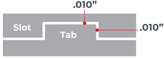
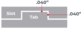
Tab and slot tolerance .010"
BENDING SPECIFICATIONS
Min bend part size .375" x 1.5"
Max bending flat part size 44" x 30"
Max bend length 44"
Min flange length (before bend/Flat Pattern) 90° or less (obtuse) 0.255"
Min flange length (after bend) 90° or less (obtuse) 0.286"
Minimum Length Center of bend line 91-130* (Acute) .332
Die width 0.472"
Effective bend radius @ 90° 0.024"
Max bend angle 130°
Bend angle tolerance (bend length up to 24″) +/- 1 degree
Bend angle tolerance (bend length over 24″) +/- 2 degrees
Bend deduction @ 90° 0.062"
K Factor 0.45
Bend relief depth 0.084"
Minimum joggle. Bend line to bend line @90° max flange 0.363"
Maximum joggle. Bend line to bend line @90° max flange 3.750"
DIMPLE SPECIFICATIONS
Min dimple part size 1.200" x 5.200"
Max dimple part size 26" x 56"
Smallest dimple .500"
Largest dimple 3.000"
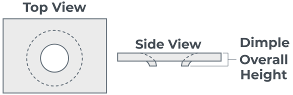
Dimple overall height (.500" dimple) .132"
Dimple overall height (.750" dimple) .130"
Dimple overall height (1.000" dimple) .178"
Dimple overall height (1.250" dimple) .188"
Dimple overall height (1.500" dimple) .200"
Dimple overall height (1.750" dimple) .210"
Dimple overall height (2.000" dimple) .230"
Dimple overall height (2.500" dimple) .288"
Dimple overall height (3.000" dimple) .370"
HARDWARE SPECIFICATIONS
Min hardware part size 1″ x 1.5″
Max hardware part size 36″ x 46″
Max 4 sided box flange height (hardware) 3"
Hardware specific specifications Please view our Hardware Catalog
TAPPING SPECIFICATIONS
Largest Tap M2.5 x 0.45
Smallest Tap 1-64
Min Flat Part Size Tapping 0.949" x 1.5"
Max Flat Part Size Tapping 36" x 46"
Tapping Min Hole to Edge 0.020"
5052 PROPERTIES
Material Composition Aluminum (Al): 95.8 – 97.7 Magnesium (Mg): 2.2 – 2.8 Chromium (Cr): 0.15 – 0.35 Iron (Fe): 0 – 0.4 Silicon (Si): 0 – 0.25 Manganese (Mn): 0 – 0.1 Zinc (Zn): 0 – 0.1 Copper (Cu): 0 – 0.1 Residuals: 0 – 0.15
Density 169.344 lb/ft^3
Heat treatments process N/A
ASTM B209-14
Tensile Strength (Ultimate) 34 ksi
Tensile Strength (Yield) 26 ksi
Shear Strength 20 ksi
Shear Modulus 3700 ksi
Fatigue Strength 17 ksi
Brinell Hardness 60
Elongation at Break 12%
Elastic Modulus 9900 ksi
Poisson’s Ratio .33
Thermal Conductivity 138 BTU/h-ft °F
Melting Point 1120 °F
Magnetic No
Does it Rust No

.063"1.60mm 5052 H32 Aluminum

Material Details & Specifications

5052 .063" General Details
Advertised Thickness 0.063"
Gauge 14
Thickness tolerance positive 0.004"
Thickness tolerance negative 0.004"
Mill Finish Cold Rolled
Top/Bottom finish Identical both sides
Sourced from Global
LASER CUTTING SPECIFICATIONS
Cutting process Fiber laser
Cut tolerance +/- 0.005"
Flatness tolerance before cutting +/-0.030 per foot
Min part size .25″ x .375″
Max part size 44″ x 30″
Recommended Min hole size .022″
Min hole size .014"
Min bridge size .024″
Min hole to edge distance .020″
Tab and slot tolerance .010"
ANODIZING SPECIFICATIONS
Min anodizing part size 1″ x 3″
Max anodizing part size 23" x 23"
BENDING SPECIFICATIONS
Min bend part size .375" x 1.5"
Max bending flat part size 44" x 30"
Max bend length 44"
Min flange length (before bend/Flat Pattern) 90° or less (obtuse) 0.255"
Min flange length (after bend) 90° or less (obtuse) 0.303"
Die width 0.472"
Effective bend radius @ 90° 0.035"
Max bend angle 130°
Bend angle tolerance (bend length up to 24″) +/- 1 degree
Bend angle tolerance (bend length over 24″) +/- 2 degrees
Bend deduction @ 90° 0.096"
K Factor 0.42
Bend relief depth 0.118"
Minimum joggle. Bend line to bend line @90° max flange 0.324"
Maximum joggle. Bend line to bend line @90° max flange 3.750"
DEBURRING SPECIFICATIONS
Min deburring part size 1" x 3"
Max deburring part size 36″ x 46″
DIMPLE SPECIFICATIONS
Min dimple part size 1.200" x 5.200"
Max dimple part size 26" x 56"
Smallest dimple .500"
Largest dimple 3.000"
Dimple overall height (.500" dimple) .153"
Dimple overall height (.750" dimple) .151"
Dimple overall height (1.000" dimple) .200"
Dimple overall height (1.250" dimple) .213"
Dimple overall height (1.500" dimple) .230"
Dimple overall height (1.750" dimple) .240"
Dimple overall height (2.000" dimple) .257"
Dimple overall height (2.500" dimple) .307"
Dimple overall height (3.000" dimple) .380"
HARDWARE SPECIFICATIONS
Min hardware part size 1″ x 1.5″
Max hardware part size 36″ x 46″
Max 4 sided box flange height (hardware) 3"
Hardware specific specifications Please view our Hardware Catalog
POWDER COATING SPECIFICATIONS
Min powder coating part size 1" x 3"
Max powder coating part size 30" x 36"
TAPPING SPECIFICATIONS
Largest Tap 10-32
Smallest Tap 1-72
Min Flat Part Size Tapping 0.949" x 1.5"
Max Flat Part Size Tapping 36" x 46"
Tapping Min Hole to Edge 0.020"
5052 PROPERTIES
Material Composition Aluminum (Al): 95.8 – 97.7 Magnesium (Mg): 2.2 – 2.8 Chromium (Cr): 0.15 – 0.35 Iron (Fe): 0 – 0.4 Silicon (Si): 0 – 0.25 Manganese (Mn): 0 – 0.1 Zinc (Zn): 0 – 0.1 Copper (Cu): 0 – 0.1 Residuals: 0 – 0.15
Density 169.344 lb/ft^3
Heat treatments process N/A
ASTM B209-14
Tensile Strength (Ultimate) 34 ksi
Tensile Strength (Yield) 26 ksi
Shear Strength 20 ksi
Shear Modulus 3700 ksi
Fatigue Strength 17 ksi
Brinell Hardness 60
Elongation at Break 12%
Elastic Modulus 9900 ksi
Poisson’s Ratio .33
Thermal Conductivity 138 BTU/h-ft °F
Melting Point 1120 °F
Magnetic No
Does it Rust No

.080"2.03mm 5052 H32 Aluminum

Material Details & Specifications

5052 .080" GENERAL DETAILS
Advertised Thickness 0.080"
Gauge 12
Thickness tolerance positive 0.005"
Thickness tolerance negative 0.005"
Mill Finish Cold Rolled
Top/Bottom finish Identical both sides
Sourced from Global
LASER CUTTING SPECIFICATIONS
Cutting process Fiber laser
Cut tolerance +/- 0.005"
Flatness tolerance before cutting +/-0.030 per foot
Min part size .25″ x .375″
Max part size 44″ x 30″
Recommended Min hole size .028″
Min hole size .014"
Min bridge size .030″
Min hole to edge distance .024″
Tab and slot tolerance .010"
ANODIZING SPECIFICATIONS
Min anodizing part size 1″ x 3″
Max anodizing part size 23" x 23"
BENDING SPECIFICATIONS
Min bend part size .375" x 1.5"
Max bending flat part size 44" x 30"
Max bend length 44"
Min flange length (before bend/Flat Pattern) 90° or less (obtuse) 0.255"
Min flange length (after bend) 90° or less (obtuse) 0.313"
Minimum Length Center of bend line 91-130° (Acute) .332"
Die width 0.472"
Effective bend radius @ 90° 0.038"
Max bend angle 130°
Bend angle tolerance (bend length up to 24″) +/- 1 degree
Bend angle tolerance (bend length over 24″) +/- 2 degrees
Bend deduction @ 90° 0.116"
K Factor 0.48
Bend relief depth 0.150"
Minimum joggle. Bend line to bend line @90° max flange 0.343"
Maximum joggle. Bend line to bend line @90° max flange 3.750"
DEBURRING SPECIFICATIONS
Min deburring part size 1" x 3"
Max deburring part size 36″ x 46″
DIMPLE SPECIFICATIONS
Min dimple part size 1.200" x 5.200"
Max dimple part size 26" x 56"
Smallest dimple .750"
Largest dimple 3.000"
Dimple overall height (.750" dimple) .175"
Dimple overall height (1.000" dimple) .215"
Dimple overall height (1.250" dimple) .225"
Dimple overall height (1.500" dimple) .250"
Dimple overall height (1.750" dimple) .265"
Dimple overall height (2.000" dimple) .278"
Dimple overall height (2.500" dimple) .327"
Dimple overall height (3.000" dimple) .400"
HARDWARE SPECIFICATIONS
Min hardware part size 1″ x 1.5″
Max hardware part size 36″ x 46″
Max 4 sided box flange height (hardware) 3"
Hardware specific specifications Please view our Hardware Catalog
POWDER COATING SPECIFICATIONS
Min powder coating part size 1" x 3"
Max powder coating part size 30" x 36"
TAPPING SPECIFICATIONS
Largest Tap 1/4-28
Smallest Tap 1-64
Min Flat Part Size Tapping 0.949" x 1.5"
Max Flat Part Size Tapping 36" x 46"
Tapping Min Hole to Edge 0.024"
Tapping Min Hole Center to Material Edge Tap hole size/2 +0.024"
5052 PROPERTIES
Material Composition Aluminum (Al): 95.8 – 97.7 Magnesium (Mg): 2.2 – 2.8 Chromium (Cr): 0.15 – 0.35 Iron (Fe): 0 – 0.4 Silicon (Si): 0 – 0.25 Manganese (Mn): 0 – 0.1 Zinc (Zn): 0 – 0.1 Copper (Cu): 0 – 0.1 Residuals: 0 – 0.15
Density 169.344 lb/ft^3
Heat treatments process N/A
ASTM B209-14
Tensile Strength (Ultimate) 34 ksi
Tensile Strength (Yield) 26 ksi
Shear Strength 20 ksi
Shear Modulus 3700 ksi
Fatigue Strength 17 ksi
Brinell Hardness 60
Elongation at Break 12%
Elastic Modulus 9900 ksi
Poisson’s Ratio .33
Thermal Conductivity 138 BTU/h-ft °F
Melting Point 1120 °F
Magnetic No
Does it Rust No

.090"2.29mm 5052 H32 Aluminum

Material Details & Specifications

5052 .090" GENERAL DETAILS
Advertised Thickness 0.090"
Gauge 11
Thickness tolerance positive 0.00"
Thickness tolerance negative 0.005"
Mill Finish Cold Rolled
Top/Bottom finish Identical both sides
Sourced from Global
LASER CUTTING SPECIFICATIONS
Cutting process Fiber laser
Cut tolerance +/- 0.005"
Flatness tolerance before cutting +/-0.030 per foot
Min part size .25″ x .375″
Max part size 44″ x 30″
Recommended Min hole size .032″
Min hole size .018"
Min bridge size .034″
Min hole to edge distance .027″
Tab and slot tolerance .010"
ANODIZING SPECIFICATIONS
Min anodizing part size 1″ x 3″
Max anodizing part size 23" x 23"
BENDING SPECIFICATIONS
Min bend part size .375" x 1.5"
Max bending flat part size 44" x 30"
Max bend length 44"
Min flange length (before bend/Flat Pattern) 90° or less (obtuse) 0.255"
Min flange length (after bend) 90° or less (obtuse) 0.326"
Minimum Length Center of bend line 91-130° (Acute) .332
Die width 0.472"
Effective bend radius @ 90° 0.032"
Max bend angle 130°
Bend angle tolerance (bend length up to 24″) +/- 1 degree
Bend angle tolerance (bend length over 24″) +/- 2 degrees
Bend deduction @ 90° 0.142"
K Factor 0.37
Bend relief depth 0.142"
Minimum joggle. Bend line to bend line @90° max flange 0.354"
Maximum joggle. Bend line to bend line @90° max flange 3.750"
DEBURRING SPECIFICATIONS
Min deburring part size 1" x 3"
Max deburring part size 36″ x 46″
DIMPLE SPECIFICATIONS
Min dimple part size 1.200" x 5.200"
Max dimple part size 26" x 56"
Smallest dimple 1.000"
Largest dimple 3.000"
Dimple overall height (1.000" dimple) .230"
Dimple overall height (1.250" dimple) .245"
Dimple overall height (1.500" dimple) .265"
Dimple overall height (1.750" dimple) .275"
Dimple overall height (2.000" dimple) .282"
Dimple overall height (2.500" dimple) .345"
Dimple overall height (3.000" dimple) .418"
HARDWARE SPECIFICATIONS
Min hardware part size 1″ x 1.5″
Max hardware part size 36″ x 46″
Max 4 sided box flange height (hardware) 3"
Hardware specific specifications Please view our Hardware Catalog
POWDER COATING SPECIFICATIONS
Min powder coating part size 1" x 3"
Max powder coating part size 30" x 36"
TAPPING SPECIFICATIONS
Largest Tap M12 x 1.0
Smallest Tap 1-64
Min Flat Part Size Tapping 0.949" x 1.5"
Max Flat Part Size Tapping 36" x 46"
Tapping Min Hole to Edge 0.027"
Tapping Min Hole Center to Material Edge Tap hole size/2 +0.027"
5052 PROPERTIES
Material Composition Aluminum (Al): 95.8 – 97.7 Magnesium (Mg): 2.2 – 2.8 Chromium (Cr): 0.15 – 0.35 Iron (Fe): 0 – 0.4 Silicon (Si): 0 – 0.25 Manganese (Mn): 0 – 0.1 Zinc (Zn): 0 – 0.1 Copper (Cu): 0 – 0.1 Residuals: 0 – 0.15
Density 169.344 lb/ft^3
Heat treatments process N/A
ASTM B209-14
Tensile Strength (Ultimate) 34 ksi
Tensile Strength (Yield) 26 ksi
Shear Strength 20 ksi
Shear Modulus 3700 ksi
Fatigue Strength 17 ksi
Brinell Hardness 60
Elongation at Break 12%
Elastic Modulus 9900 ksi
Poisson’s Ratio .33
Thermal Conductivity 138 BTU/h-ft °F
Melting Point 1120 °F
Magnetic No
Does it Rust No

.100"2.54mm 5052 H32 Aluminum

Material Details & Specifications

5052 .100" GENERAL DETAILS
Advertised Thickness 0.100"
Gauge 10
Thickness tolerance positive 0.006"
Thickness tolerance negative 0.006"
Mill Finish Cold Rolled
Top/Bottom finish Identical both sides
Sourced from Global
LASER CUTTING SPECIFICATIONS
Cutting process Fiber laser
Cut tolerance +/- 0.005"
Flatness tolerance before cutting +/-0.030 per foot
Min part size .25″ x .375″
Max part size 44″ x 30″
Recommended Min hole size .035″
Min hole size .023"
Min bridge size .038″
Min hole to edge distance .030″
Tab and slot tolerance .010"
ANODIZING SPECIFICATIONS
Min anodizing part size 1″ x 3″
Max anodizing part size 23" x 23"
BENDING SPECIFICATIONS
Min bend part size .375" x 1.5"
Max bending flat part size 44" x 30"
Max bend length 44"
Min flange length (before bend/Flat Pattern) 90° or less (obtuse) 0.368"
Min flange length (after bend) 90° or less (obtuse) 0.463"
Minimum Length Center of bend line 91-130* (Acute) 0.478"
Die width 0.630"
Effective bend radius @ 90° 0.125"
Max bend angle 130°
Bend angle tolerance (bend length up to 24″) +/- 1 degree
Bend angle tolerance (bend length over 24″) +/- 2 degrees
Bend deduction @ 90° 0.191"
K Factor 0.40
Bend relief depth 0.245"
Minimum joggle. Bend line to bend line @90° max flange 0.478"
Maximum joggle. Bend line to bend line @90° max flange 3.750"
DEBURRING SPECIFICATIONS
Min deburring part size 1" x 3"
Max deburring part size 36″ x 46″
DIMPLE SPECIFICATIONS
Min dimple part size 1.200" x 5.200"
Max dimple part size 26" x 56"
Smallest dimple 1.000"
Largest dimple 3.000"
Dimple overall height (1.000" dimple) .220"
Dimple overall height (1.250" dimple) .250"
Dimple overall height (1.500" dimple) .265"
Dimple overall height (1.750" dimple) .285"
Dimple overall height (2.000" dimple) .295"
Dimple overall height (2.500" dimple) .350"
Dimple overall height (3.000" dimple) .415"
HARDWARE SPECIFICATIONS
Min hardware part size 1″ x 1.5″
Max hardware part size 36″ x 46″
Max 4 sided box flange height (hardware) 3"
Hardware specific specifications Please view our Hardware Catalog
PLATING SPECIFICATIONS
Min Plating Part Size 1″ x 3″
Max Plating Part Size 23″ x 23″
POWDER COATING SPECIFICATIONS
Min powder coating part size 1" x 3"
Max powder coating part size 30" x 36"
TAPPING SPECIFICATIONS
Largest Tap 1/4-28
Smallest Tap M2 x 0.4
Min Flat Part Size Tapping 0.949" x 1.5"
Max Flat Part Size Tapping 36" x 46"
Tapping Min Hole to Edge 0.030"
Tapping Min Hole Center to Material Edge Tap hole size/2 +0.030"
5052 PROPERTIES
Material Composition Aluminum (Al): 95.8 – 97.7 Magnesium (Mg): 2.2 – 2.8 Chromium (Cr): 0.15 – 0.35 Iron (Fe): 0 – 0.4 Silicon (Si): 0 – 0.25 Manganese (Mn): 0 – 0.1 Zinc (Zn): 0 – 0.1 Copper (Cu): 0 – 0.1 Residuals: 0 – 0.15
Density 169.344 lb/ft^3
Heat treatments process N/A
ASTM B209-14
Tensile Strength (Ultimate) 34 ksi
Tensile Strength (Yield) 26 ksi
Shear Strength 20 ksi
Shear Modulus 3700 ksi
Fatigue Strength 17 ksi
Brinell Hardness 60
Elongation at Break 12%
Elastic Modulus 9900 ksi
Poisson’s Ratio .33
Thermal Conductivity 138 BTU/h-ft °F
Melting Point 1120 °F
Magnetic No
Does it Rust No

.125"3.18mm 5052 H32 Aluminum

Material Details & Specifications

5052 .125" General Details
Advertised Thickness 0.125"
Gauge 8
Thickness tolerance positive 0.006"
Thickness tolerance negative 0.006"
Mill Finish Cold Rolled
Top/Bottom finish Identical both sides
Sourced from Global
LASER CUTTING SPECIFICATIONS
Cutting process Fiber laser
Cut tolerance +/- 0.005"
Flatness tolerance before cutting +/-0.030 per foot
Min part size .25″ x .375″
Max part size 44″ x 30″
Recommended Min hole size .044″
Min hole size .032"
Min bridge size .048″
Min hole to edge distance .038″
Tab and slot tolerance .010"
ANODIZING SPECIFICATIONS
Min anodizing part size 1″ x 3″
Max anodizing part size 23" x 23"
BENDING SPECIFICATIONS
Min bend part size .375" x 1.5"
Max bending flat part size 44" x 30"
Max bend length 44"
Min flange length (before bend/Flat Pattern) 90° or less (obtuse) 0.368"
Min flange length (after bend) 90° or less (obtuse) 0.476"
Minimum Length Center of bend line 91-130* (Acute) .478
Die width 0.630"
Effective bend radius @ 90° 0.125"
Max bend angle 130°
Bend angle tolerance (bend length up to 24″) +/- 1 degree
Bend angle tolerance (bend length over 24″) +/- 2 degrees
Bend deduction @ 90° 0.216"
K Factor 0.44
Bend relief depth 0.270"
Minimum joggle. Bend line to bend line @90° max flange 0.506"
Maximum joggle. Bend line to bend line @90° max flange 3.750"
COUNTERSINK SPECIFICATIONS
Min countersink part size 1" x 4"
Max countersink part size 14″ x 46″
Countersink Min Minor .099"
Countersink Max Major .472″
Countersink Min Hole Center to Material Edge .246"
DEBURRING SPECIFICATIONS
Min deburring part size 1" x 3"
Max deburring part size 36″ x 46″
DIMPLE SPECIFICATIONS
Min dimple part size 1.200" x 5.200"
Max dimple part size 26" x 56"
Smallest dimple 1.250"
Largest dimple 3.000"
Dimple overall height (1.250" dimple) 0.275"
Dimple overall height (1.500" dimple) .295"
Dimple overall height (1.750" dimple) .315"
Dimple overall height (2.000" dimple) .330"
Dimple overall height (2.500" dimple) .375"
Dimple overall height (3.000" dimple) .450"
HARDWARE SPECIFICATIONS
Min hardware part size 1″ x 1.5″
Max hardware part size 36″ x 46″
Max 4 sided box flange height (hardware) 3"
Hardware specific specifications Please view our Hardware Catalog
POWDER COATING SPECIFICATIONS
Min powder coating part size 1" x 3"
Max powder coating part size 30" x 36"
TAPPING SPECIFICATIONS
Largest Tap M10 x 1.5
Smallest Tap M2 x 0.4
Min Flat Part Size Tapping 0.949" x 1.5"
Max Flat Part Size Tapping 36" x 46"
Tapping Min Hole to Edge 0.038"
Tapping Min Hole Center to Material Edge Tap hole size/2 +0.038"
TUMBLE SPECIFICATIONS
Min Part Size Tumbling 0.5″ x 1.5″
Max Part Size Tumbling 4″ x 7″
5052 PROPERTIES
Material Composition Aluminum (Al): 95.8 – 97.7 Magnesium (Mg): 2.2 – 2.8 Chromium (Cr): 0.15 – 0.35 Iron (Fe): 0 – 0.4 Silicon (Si): 0 – 0.25 Manganese (Mn): 0 – 0.1 Zinc (Zn): 0 – 0.1 Copper (Cu): 0 – 0.1 Residuals: 0 – 0.15
Density 169.344 lb/ft^3
Heat treatments process N/A
ASTM B209-14
Tensile Strength (Ultimate) 34 ksi
Tensile Strength (Yield) 26 ksi
Shear Strength 20 ksi
Shear Modulus 3700 ksi
Fatigue Strength 17 ksi
Brinell Hardness 60
Elongation at Break 12%
Elastic Modulus 9900 ksi
Poisson’s Ratio .33
Thermal Conductivity 138 BTU/h-ft °F
Melting Point 1120 °F
Magnetic No
Does it Rust No

.187"4.75mm 5052 H32 Aluminum

Material Details & Specifications

5052 .187" GENERAL DETAILS
Advertised Thickness 0.187"
Gauge N/A
Thickness tolerance positive 0.009"
Thickness tolerance negative 0.009"
Top/Bottom finish Identical both sides
Sourced from Global
LASER CUTTING SPECIFICATIONS
Cutting process Fiber laser
Cut tolerance +/- 0.005"
Flatness tolerance before cutting +/-0.030 per foot
Min part size .500″ x .750″
Max part size 44″ x 30″
Recommended Min hole size .065″
Min hole size .042"
Min bridge size .071″
Min hole to edge distance .056″
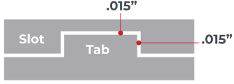
Tab and slot tolerance .015"
ANODIZING SPECIFICATIONS
Min anodizing part size 1″ x 3″
Max anodizing part size 23" x 23"
BENDING SPECIFICATIONS
Min bend part size .375" x 1.5"
Max bending flat part size 44" x 30"
Max bend length 44"
Min flange length (before bend/Flat Pattern) 90° or less (obtuse) 0.620"
Min flange length (after bend) 90° or less (obtuse) 0.798"
Minimum Length Center of bend line 91-130* (Acute) N/A
Die width 0.984"
Effective bend radius @ 90° 0.250"
Max bend angle 90°
Bend angle tolerance (bend length up to 24″) +/- 1 degree
Bend angle tolerance (bend length over 24″) +/- 2 degrees
Bend deduction @ 90° 0.356"
K Factor 0.43
Bend relief depth 0.457"
Minimum joggle. Bend line to bend line @90° max flange 0.826"
Maximum joggle. Bend line to bend line @90° max flange 3.750"
COUNTERSINK SPECIFICATIONS
Min countersink part size 1" x 4"
Max countersink part size 14″ x 46″
Countersink Min Minor .099"
Countersink Max Major .531″
Countersink Min Hole Center to Material Edge .276"
DEBURRING SPECIFICATIONS
Min deburring part size 1" x 3"
Max deburring part size 36″ x 46″
HARDWARE SPECIFICATIONS
Min hardware part size 1″ x 1.5″
Max hardware part size 36″ x 46″
Max 4 sided box flange height (hardware 3"
Hardware specific specifications Please view our Hardware Catalog
POWDER COATING SPECIFICATIONS
Min powder coating part size 1" x 3"
Max powder coating part size 30" x 36"
TAPPING SPECIFICATIONS
Largest Tap 1/2-20
Smallest Tap 4-40
Min Flat Part Size Tapping 0.949" x 1.5"
Max Flat Part Size Tapping 36" x 46"
Tapping Min Hole to Edge 0.056"
Tapping Min Hole Center to Material Edge Tap hole size/2 +0.056"
TUMBLE SPECIFICATIONS
Min Part Size Tumbling 0.5″ x 1.5″
Max Part Size Tumbling 4″ x 7″
5052 PROPERTIES
Material Composition Aluminum (Al): 95.8 – 97.7 Magnesium (Mg): 2.2 – 2.8 Chromium (Cr): 0.15 – 0.35 Iron (Fe): 0 – 0.4 Silicon (Si): 0 – 0.25 Manganese (Mn): 0 – 0.1 Zinc (Zn): 0 – 0.1 Copper (Cu): 0 – 0.1 Residuals: 0 – 0.15
Density 169.344 lb/ft^3
Heat treatments process N/A
ASTM B209-14
Tensile Strength (Ultimate) 34 ksi
Tensile Strength (Yield) 26 ksi
Shear Strength 20 ksi
Shear Modulus 3700 ksi
Fatigue Strength 17 ksi
Brinell Hardness 60
Elongation at Break 12%
Elastic Modulus 9900 ksi
Poisson’s Ratio .33
Thermal Conductivity 138 BTU/h-ft °F
Melting Point 1120 °F
Magnetic No
Does it Rust No

.250"6.35mm 5052 H32 Aluminum

Material Details & Specifications

5052 .250" GENERAL DETAILS
Advertised Thickness 0.250"
Gauge N/A
Thickness tolerance positive 0.027"
Thickness tolerance negative 0.027"
Sourced from Global
LASER CUTTING SPECIFICATIONS
Cutting process Fiber laser
Cut tolerance +/- 0.005"
Flatness tolerance before cutting +/-0.030 per foot
Min part size .500″ x .750″
Max part size 44″ x 30″
Recommended Min hole size .088″
Min hole size .057"
Min bridge size .095″
Min hole to edge distance .075″
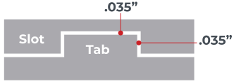
Tab and slot tolerance .035"
ANODIZING SPECIFICATIONS
Min anodizing part size 1″ x 3″
Max anodizing part size 23" x 23"
BENDING SPECIFICATIONS
Min bend part size .375" x 1.5"
Max bending flat part size 44" x 30"
Max bend length 44"
Min flange length (before bend/Flat Pattern) 90° or less (obtuse) 1.150"
Min flange length (after bend) 90° or less (obtuse) 1.371"
Minimum Length Center of bend line 91-130* (Acute) N/A
Die width 1.575"
Effective bend radius @ 90° 0.250"
Max bend angle 90°
Bend angle tolerance (bend length up to 24″) +/- 1 degree
Bend angle tolerance (bend length over 24″) +/- 2 degrees
Bend deduction @ 90° 0.442"
K Factor 0.42
Bend relief depth 0.520"
Minimum joggle. Bend line to bend line @90° max flange 1.425"
Maximum joggle. Bend line to bend line @90° max flange 3.750"
COUNTERSINK SPECIFICATIONS
Min countersink part size 1" x 4"
Max countersink part size 14″ x 46″
Countersink Min Minor .099"
Countersink Max Major .656″
Countersink Min Hole Center to Material Edge .338"
DEBURRING SPECIFICATIONS
Min deburring part size 1" x 3"
Max deburring part size 36″ x 46″
HARDWARE SPECIFICATIONS
Min hardware part size 1″ x 1.5″
Max hardware part size 36″ x 46″
Max 4 sided box flange height (hardware 3"
Hardware specific specifications Please view our Hardware Catalog
POWDER COATING SPECIFICATIONS
Min powder coating part size 1" x 3"
Max powder coating part size 30" x 36"
TAPPING SPECIFICATIONS
Largest Tap 1/2-20
Smallest Tap 4-40
Min Flat Part Size Tapping 0.949" x 1.5"
Max Flat Part Size Tapping 36" x 46"
Tapping Min Hole to Edge 0.075"
Tapping Min Hole Center to Material Edge Tap hole size/2 +0.075"
TUMBLE SPECIFICATIONS
Min Part Size Tumbling 0.5″ x 1.5″
Max Part Size Tumbling 4″ x 7″
5052 PROPERTIES
Material Composition Aluminum (Al): 95.8 – 97.7 Magnesium (Mg): 2.2 – 2.8 Chromium (Cr): 0.15 – 0.35 Iron (Fe): 0 – 0.4 Silicon (Si): 0 – 0.25 Manganese (Mn): 0 – 0.1 Zinc (Zn): 0 – 0.1 Copper (Cu): 0 – 0.1 Residuals: 0 – 0.15
Density 169.344 lb/ft^3
Heat treatments process N/A
ASTM B209-14
Tensile Strength (Ultimate) 34 ksi
Tensile Strength (Yield) 26 ksi
Shear Strength 20 ksi
Shear Modulus 3700 ksi
Fatigue Strength 17 ksi
Brinell Hardness 60
Elongation at Break 12%
Elastic Modulus 9900 ksi
Poisson’s Ratio .33
Thermal Conductivity 138 BTU/h-ft °F
Melting Point 1120 °F
Magnetic No
Does it Rust No

.313"8.0mm 5052 H32 Aluminum

Material Details & Specifications

5052 .313" GENERAL DETAILS
Advertised Thickness 0.313"
Gauge N/A
Thickness tolerance positive 0.014"
Thickness tolerance negative 0.014"
Sourced from Global
LASER CUTTING SPECIFICATIONS
Cutting process Fiber laser
Cut tolerance +/- 0.005"
Flatness tolerance before cutting +/-0.030 per foot
Min part size .500″ x .750″
Max part size 44″ x 30″
Recommended Min hole size .090″
Min hole size .075"
Min bridge size .125″
Min hole to edge distance .094″
Tab and slot tolerance .035"
ANODIZING SPECIFICATIONS
Min anodizing part size 1″ x 3″
Max anodizing part size 23" x 23"
COUNTERSINK SPECIFICATIONS
Min countersink part size 1" x 4"
Max countersink part size 14″ x 46″
Countersink Min Minor .099"
Countersink Max Major .656″
Countersink Min Hole Center to Material Edge .338"
DEBURRING SPECIFICATIONS
Min deburring part size 1" x 3"
Max deburring part size 36″ x 46″
HARDWARE SPECIFICATIONS
Min hardware part size 1″ x 1.5″
Max hardware part size 36″ x 46″
Max 4 sided box flange height (hardware 3"
Hardware specific specifications Please view our Hardware Catalog
POWDER COATING SPECIFICATIONS
Min powder coating part size 1" x 3"
Max powder coating part size 30" x 36"
TAPPING SPECIFICATIONS
Largest Tap 1/2-20
Smallest Tap 4-40
Min Flat Part Size Tapping 0.949" x 1.5"
Max Flat Part Size Tapping 36" x 46"
Tapping Min Hole to Edge 0.094"
Tapping Min Hole Center to Material Edge Tap hole size/2 +0.075"
TUMBLE SPECIFICATIONS
Min Part Size Tumbling 0.5″ x 1.5″
Max Part Size Tumbling 4″ x 7″
5052 PROPERTIES
Material Composition Aluminum (Al): 95.8 – 97.7 Magnesium (Mg): 2.2 – 2.8 Chromium (Cr): 0.15 – 0.35 Iron (Fe): 0 – 0.4 Silicon (Si): 0 – 0.25 Manganese (Mn): 0 – 0.1 Zinc (Zn): 0 – 0.1 Copper (Cu): 0 – 0.1 Residuals: 0 – 0.15
Density 169.344 lb/ft^3
Heat treatments process N/A
ASTM B209-14
Tensile Strength (Ultimate) 34 ksi
Tensile Strength (Yield) 26 ksi
Shear Strength 20 ksi
Shear Modulus 3700 ksi
Fatigue Strength 17 ksi
Brinell Hardness 60
Elongation at Break 12%
Elastic Modulus 9900 ksi
Poisson’s Ratio .33
Thermal Conductivity 138 BTU/h-ft °F
Melting Point 1120 °F
Magnetic No
Does it Rust No

.375"9.5mm 5052 H32 Aluminum

Material Details & Specifications

5052 .375" GENERAL DETAILS
Advertised Thickness 0.375"
Gauge N/A
Thickness tolerance positive 0.033"
Thickness tolerance negative 0.033"
Top/Bottom finish Identical both sides
Sourced from Global
LASER CUTTING SPECIFICATIONS
Cutting process Fiber laser
Cut tolerance +/- 0.005"
Flatness tolerance before cutting +/-0.030 per foot
Min part size .75″ x 1.00″
Max part size 44″ x 30″
Recommended Min hole size .130″
Min hole size .085"
Min bridge size .143″
Min hole to edge distance .113″
Tab and slot tolerance .040"
ANODIZING SPECIFICATIONS
Min anodizing part size 1″ x 3″
Max anodizing part size 23" x 23"
COUNTERSINK SPECIFICATIONS
Min countersink part size 1" x 4"
Max countersink part size 14″ x 46″
Countersink Min Minor .130"
Countersink Max Major .656″
Countersink Min Hole Center to Material Edge .338"
DEBURRING SPECIFICATIONS
Min deburring part size 1" x 3"
Max deburring part size 36″ x 46″
HARDWARE SPECIFICATIONS
Min hardware part size 1″ x 1.5″
Max hardware part size 36″ x 46″
Max 4 sided box flange height (hardware N/A
Hardware specific specifications Please view our Hardware Catalog
POWDER COATING SPECIFICATIONS
Min powder coating part size 1" x 3"
Max powder coating part size 30" x 36"
TAPPING SPECIFICATIONS
Largest Tap 12/20
Smallest Tap 8-32
Min Flat Part Size Tapping 0.949" x 1.5"
Max Flat Part Size Tapping 36" x 46"
Tapping Min Hole to Edge 0.113"
Tapping Min Hole Center to Material Edge Tap hole size/2 +0.113"
TUMBLE SPECIFICATIONS
Min Part Size Tumbling 0.5″ x 1.5″
Max Part Size Tumbling 4″ x 7″
5052 PROPERTIES
Material Composition Aluminum (Al): 95.8 – 97.7 Magnesium (Mg): 2.2 – 2.8 Chromium (Cr): 0.15 – 0.35 Iron (Fe): 0 – 0.4 Silicon (Si): 0 – 0.25 Manganese (Mn): 0 – 0.1 Zinc (Zn): 0 – 0.1 Copper (Cu): 0 – 0.1 Residuals: 0 – 0.15
Density 169.344 lb/ft^3
Heat treatments process N/A
ASTM B209-14
Tensile Strength (Ultimate) 34 ksi
Tensile Strength (Yield) 26 ksi
Shear Strength 20 ksi
Shear Modulus 3700 ksi
Fatigue Strength 17 ksi
Brinell Hardness 60
Elongation at Break 12%
Elastic Modulus 9900 ksi
Poisson’s Ratio .33
Thermal Conductivity 138 BTU/h-ft °F
Melting Point 1120 °F
Magnetic No
Does it Rust No

.500"12.7mm 5052 H32 Aluminum

Material Details & Specifications

5052 .500" GENERAL DETAILS
Advertised Thickness 0.500"
Gauge N/A
Thickness tolerance positive 0.043"
Thickness tolerance negative 0.043"
Top/Bottom finish Identical both sides
Sourced from Global
LASER CUTTING SPECIFICATIONS
Cutting process Fiber laser
Cut tolerance +/- 0.005"
Flatness tolerance before cutting +/-0.030 per foot
Min part size 1.00″ x 1.00″
Max part size 44″ x 30″
Recommended Min hole size .170″
Min hole size .125"
Min bridge size .190″
Min hole to edge distance .150″
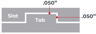
Tab and slot tolerance .050"
ANODIZING SPECIFICATIONS
Min anodizing part size 1″ x 3″
Max anodizing part size 23" x 23"
COUNTERSINK SPECIFICATIONS
Min countersink part size 1" x 4"
Max countersink part size 14″ x 46″
Countersink Min Minor .193"
Countersink Max Major .656″
Countersink Min Hole Center to Material Edge .338"
DEBURRING SPECIFICATIONS
Min deburring part size 1" x 3"
Max deburring part size 36″ x 46″
HARDWARE SPECIFICATIONS
Min hardware part size 1″ x 1.5″
Max hardware part size 36″ x 46″
Max 4 sided box flange height (hardware N/A
Hardware specific specifications Please view our Hardware Catalog
POWDER COATING SPECIFICATIONS
Min powder coating part size 1" x 3"
Max powder coating part size 30" x 36"
TAPPING SPECIFICATIONS
Largest Tap 1/2-20
Smallest Tap 10-32
Min Flat Part Size Tapping 0.949" x 1.5"
Max Flat Part Size Tapping 36" x 46"
Tapping Min Hole to Edge 0.150"
Tapping Min Hole Center to Material Edge Tap hole size/2 +0.150"
TUMBLE SPECIFICATIONS
Min Part Size Tumbling 0.5″ x 1.5″
Max Part Size Tumbling 4″ x 7″
5052 PROPERTIES
Material Composition Aluminum (Al): 95.8 – 97.7 Magnesium (Mg): 2.2 – 2.8 Chromium (Cr): 0.15 – 0.35 Iron (Fe): 0 – 0.4 Silicon (Si): 0 – 0.25 Manganese (Mn): 0 – 0.1 Zinc (Zn): 0 – 0.1 Copper (Cu): 0 – 0.1 Residuals: 0 – 0.15
Density 169.344 lb/ft^3
Heat treatments process N/A
ASTM B209-14
Tensile Strength (Ultimate) 34 ksi
Tensile Strength (Yield) 26 ksi
Shear Strength 20 ksi
Shear Modulus 3700 ksi
Fatigue Strength 17 ksi
Brinell Hardness 60
Elongation at Break 12%
Elastic Modulus 9900 ksi
Poisson’s Ratio .33
Thermal Conductivity 138 BTU/h-ft °F
Melting Point 1120 °F
Magnetic No
Does it Rust No
What is 5052 H32 Aluminum?

What is 5052 H32 Aluminum?

5052 H32 aluminum is strong, inexpensive, and lightweight. Whether you’re welding, machining, or bending, 5052 aluminum is going to be the go-to material for those projects that need excellent all-around material properties. Our laser cut 5052 aluminum is exceptionally lightweight and strong, making it perfect for projects where overall load is a concern.

What can you make with 5052 H32 Aluminum parts?

With high relative ultimate strength (and fatigue strength), 5052 aluminum has a number of practical usages. It is non-heat treatable, which means that it is cold-worked to achieve its moderate-to-high strength properties. For greater strength, check out our 6061 series aluminum.

  • Robotics
  • Fences
  • Signage
  • Hinges
  • Marine applications
  • Heat exchangers
  • Signage
  • Panels
  • And so much more!

5052 H32 Aluminum FAQs

SendCutSend offers 5052 H32 Aluminum in ten thickness options: .040″ (1.02mm), .063″ (1.60mm), .080″ (2.03mm), .090″ (2.29mm), .100″ (2.54mm), .125″ (3.18mm), .187″ (4.75mm), .250″ (6.35mm), .375″(9.5mm), .500″ (12.7mm).

5052 H32 Aluminum is available at SendCutSend with a range of thicknesses and part sizes. Instant quotes are possible for dimensions between .25″ x .375″ and 30″ x 44″, while custom quoting extends the maximum size to 30″ x 56″

You can add the following services to your 5052 H32 Aluminum parts: Anodizing, Bending, Deburring, Countersinking, Deburring, Engraving, Dimple Forming, Hardware Insertion, Powder Coating, Tapping, Tumbling, and Welding

Start your first Metal Manufacturing project today!

Upload your CAD design, or try one of our customizable part templates to get instant pricing on your custom laser cut parts. All delivered to your door in a matter of days.

Waterjet

Upload a CAD file

We accept .ai, .dxf, .dwg, .eps, .stp, and .step

Start Your Quote

5052 Aluminum sheet: strength, bending, and laser cutting guide

5052 aluminum is one of the most versatile and widely used aluminum alloys in fabrication. At SendCutSend, it’s also our most popular aluminum sheet metal option. Designers choose it because of its excellent corrosion resistance, good workability, and reliable strength for a wide range of projects.

Below you’ll find a comprehensive guide to 5052 aluminum—covering its properties, fabrication characteristics, and the most common questions customers ask before designing their parts.

Key things to know about 5052 Aluminum

  • Excellent corrosion resistance thanks to its magnesium content, ideal for marine and outdoor applications.
  • Not heat-treatable—strength comes from cold working, not heat treatment.
  • Highly formable—superior bendability compared to 6061 and many other alloys.
  • Laser-cuttable to ±.005” tolerance at SendCutSend in thicknesses from .040″–.500″.
  • Good weldability with MIG and TIG processes, though properties vary depending on filler alloy.
  • Cost-effective and widely available, making it a practical choice for prototyping and production.

Mechanical properties of 5052 Aluminum

When you’re selecting a material, understanding its mechanical properties is critical.

  • Tensile Strength (Ultimate): ~33,000 psi (depending on temper)
  • Yield Strength: ~28,000 psi
  • Elongation at Break: 12–20% (excellent ductility)
  • Hardness: Brinell ~60
  • Density: 0.097 lb/in³ (lightweight like most aluminums)

These properties make 5052 aluminum strong enough for enclosures, brackets, and automotive parts, but still formable enough for complex bends. Compared to 6061, it’s slightly weaker but much more forgiving to bend and shape.

Is 5052 Aluminum heat treatable?

No. Unlike alloys such as 6061, 5052 is not heat-treatable. Its strength comes from strain hardening (cold working) rather than heat treatment.

  • This is an important distinction:
  • You can’t strengthen 5052 further with heat.
  • Mechanical strength is tied to the temper (e.g., H32, H34).
  • The as-supplied strength is usually sufficient for sheet metal parts, especially when corrosion resistance and bendability matter more than ultimate tensile strength.

5052 vs. 6061 Aluminum: which should you choose?

This is one of the most common comparisons. Here’s how 5052 stacks up against 6061:

  • Strength: 6061 is stronger (tensile strength up to 45,000 psi vs. 33,000 psi).
  • Formability: 5052 wins—6061 tends to crack if bent tightly, while 5052 bends easily.
  • Corrosion Resistance: 5052 outperforms 6061, especially in marine or saltwater environments.
  • Machinability: 6061 machines more cleanly; 5052 is considered “gummier” and prone to built-up edges during milling.
  • Weldability: Both weld well, but 5052 tends to resist corrosion better post-weld.
  • Cost & Availability: Both are common and affordable, though 5052 may be cheaper in thinner sheet stock.

In short:

  • Choose 5052 for sheet metal parts requiring bends, corrosion resistance, and good weldability.
  • Choose 6061 for parts requiring higher strength and extensive machining.

Corrosion resistance: why 5052 excels outdoors

One of the standout features of 5052 aluminum is its corrosion resistance, especially in marine environments. The magnesium in its chemistry provides excellent protection against saltwater and other aggressive environments.

Applications where 5052 is favored:

  • Marine panels, boat parts, docks
  • Outdoor enclosures and housings
  • Transportation components exposed to road salts
  • Signage and architectural panels

If your parts will see long-term outdoor use, 5052 is one of the best aluminum alloys available.

Bending radius and formability

When it comes to sheet metal design, bendability is often the deciding factor between alloys. 5052 is among the most formable aluminums.

  • Minimum inside bend radius: As low as 1x material thickness in many cases (depending on temper).
  • Crack resistance: Much better than 6061, which is notorious for cracking along bends.
  • Repeatability: Consistent bend results across multiple parts, making it a reliable choice for production runs.

If you’re designing enclosures, brackets, or bent sheet parts, 5052 is an excellent option.

Machining and cutting 5052 Aluminum

Laser cutting

5052 aluminum cuts cleanly with high-powered industrial lasers. At SendCutSend, we cut 5052 up to .500″ thick with ±.005″ tolerance.

Edge quality:

  • Thin gauges (.040″–.125″): smooth edges with minimal burr.
  • Thicker gauges (.250″–.500″): some dross may appear but can usually be removed easily.

CNC Machining

5052 can be milled, drilled, and tapped, but machinists often call it “gummy.” It tends to:

  • Form built-up edges on tooling.
  • Require sharp carbide tools and high cutting speeds.
  • Benefit from lubricants to reduce chip welding.

For heavily machined components, 6061 is better. For laser-cut sheet metal parts, 5052 is the clear winner.

Welding 5052 Aluminum

5052 aluminum is very weldable:

  • Works well with MIG and TIG processes.
  • Preferred filler metals: 5356 or 5183.
  • Post-weld strength is slightly reduced, but corrosion resistance remains excellent.

This makes 5052 a top choice for welded enclosures, automotive parts, and structural assemblies that need durability outdoors.

Minimum features and hole sizes in 5052

Designers often ask about minimum cut sizes and DFM rules for aluminum sheet.

At SendCutSend:

  • Minimum hole size: Equal to material thickness (e.g., .125″ hole in .125″ sheet).
  • Minimum slot width: Material thickness or larger for clean results.
  • Spacing from edges: Leave at least 2x thickness between a hole and an edge.

These rules reduce the risk of warping, cracking, or weak edges in your parts.

Anodizing and finishing 5052 Aluminum

5052 takes surface finishes well, including:

  • Anodizing: Produces a matte, slightly less shiny appearance than 6061, but with excellent corrosion protection.
  • Powder Coating: Provides durable color and additional environmental resistance.
  • Painting: Works well after surface prep.

At SendCutSend, powder coating is a popular choice for customers ordering 5052 parts. We also offer anodizing for 5052 aluminum.

Is 5052 Aluminum food-safe?

Yes, 5052 aluminum is considered food-safe when properly finished. It’s often used in kitchen equipment, beverage cans (different alloyed temper), and food-handling enclosures.

For direct food-contact applications, a surface treatment like anodizing or powder coating is often applied for additional safety and durability.

Temperature extremes: cold and heat performance

How does 5052 behave in extreme conditions?

  • Cold: 5052 retains ductility and toughness even at very low temperatures. It resists brittle fracture better than many steels.
  • Heat: Continuous service temperature is limited to ~300°F (150°C). Beyond this, strength decreases and warping can occur.

That makes 5052 reliable for outdoor and automotive use, but not suitable for high-heat applications near engines or exhaust systems.

Safety and handling considerations

When fabricating 5052 aluminum:

  • Laser cutting produces reflective light—industrial systems must be used safely.
  • Edges are sharp after cutting; deburring may be necessary.
  • Welding fumes should be properly ventilated.
  • Powder or fine dust from machining can pose explosion hazards in enclosed spaces.

At SendCutSend, parts are cut and shipped ready-to-use, reducing risk for the end user.

When to cut 5052 Aluminum at home vs. outsource

You may wonder if you should cut 5052 aluminum yourself or outsource.

  • Cutting at home works if you have access to a CNC router or small laser, and your project is small-scale with looser tolerances.
  • Outsourcing to SendCutSend is the right move if you need:
    • Precision tolerances (±.005″)
    • Complex geometries
    • Fast turnaround (2–4 days)
    • Access to multiple thicknesses up to .500″
    • Consistent quality across production batches

For professional-grade parts, outsourcing saves time and produces better results.

Conclusion: why choose 5052 Aluminum

5052 aluminum strikes a balance that few other alloys can match. It’s strong enough for enclosures, panels, and brackets, but flexible enough to bend without cracking. It resists corrosion better than most aluminum alloys, making it a natural fit for marine and outdoor environments. And while it doesn’t machine quite as cleanly as 6061, its weldability and formability make it one of the most reliable sheet metals for laser cutting and fabrication.

At SendCutSend, we stock 5052 aluminum in 10 thicknesses from .040″ to .500″, cut it to a tight ±.005″ tolerance, and ship most orders in just 2–4 days. Whether you’re prototyping a custom bracket, building weather-resistant enclosures, or scaling up production parts, 5052 aluminum is a cost-effective, versatile choice that performs in the shop and in the field.
KH-TAT Electronic

Tell Us Your Requirements

For more information about KH-TAT Electronic CNC Tool’s cutting tool solutions, including standard and custom carbide drills, end mills, coatings, and machining support, please feel free to contact our team.
  • Email Brian@wjwanjia.com
  • WhatsApp +86 18967883827
  • Address No. 26, Fenghuang Second Street, Yongchuan District, Chongqing (within Fenghuang Lake Industrial Park, Yongchuan Industrial Park, Chongqing)

    Room 2008, North Building, Yinzhou Chamber of Commerce Building, Yinzhou District, Ningbo City, Zhejiang Province

    Nong Bon Daeng 13, Nong Bon Daeng, Ban Bang Xian, Chon buri 20170, Thailand

This site uses cookies

We use cookies to collect information about how you use this site. We use this information to make the website work as well as possible and improve our services.more details