Mild Steel size and thickness options

Cold Rolled (1008)

  • Automotive body panels
  • Ductwork
  • Furniture components
  • Shelving units
  • Computer chassis
  • Control panels
  • Brackets
  • Electronics casings
  • Automotive chassis components

HRP&O (A36/A1018)

  • Automotive structural parts
  • Structural beams
  • Bracing
  • Machine bases
  • Couplings
  • Crane components
  • Brackets
  • Automotive chassis components
  • Welded assemblies

Mild Steel material details and specifications

.030".76mm Mild Steel

Material Details & Specifications

A1008 Mild Steel 0.030" GENERAL DETAILS
Advertised Thickness 0.030"
Gauge 22
Thickness tolerance positive 0.003"
Thickness tolerance negative 0.003"
Mill Finish Cold Rolled
Top/Bottom finish Identical both sides
Sourced from Global
LASER CUTTING SPECIFICATIONS
Cutting process Fiber laser
Cut tolerance +/- 0.005"
Flatness tolerance before cutting +/-0.030 per foot
Min part size .25″ x .375″
Max part size 44″ x 30″
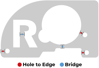
Min hole size .015″
Min bridge size .015″
Min hole to edge distance .020″
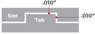
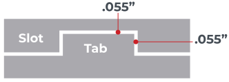
Tab and slot tolerance .010"
BENDING SPECIFICATIONS
Min bend part size .375" x 1.5"
Max bending flat part size 44" x 30"
Max bend length 44"
Min flange length (before bend/Flat Pattern) 90° or less (obtuse) 0.255"
Min flange length (after bend) 90° or less (obtuse) 0.286"
Minimum Length Center of bend line 91-130* (Acute) 0.344"
Die width 0.472"
Effective bend radius @ 90° 0.045"
Max bend angle 130°
Minimum bend angle 5°
Bend angle tolerance (bend length up to 24″) +/- 1 degree
Bend angle tolerance (bend length over 24″) +/- 2 degrees
Bend deduction @ 90° 0.061"
K Factor 0.38
Bend relief depth 0.095"
Minimum joggle. Bend line to bend line @90° max flange 0.288"
Maximum joggle. Bend line to bend line @90° max flange 3.750"
A1008 Mild Steel 0.030" GENERAL DETAILS
Advertised Thickness 0.030"
Gauge 22
Thickness tolerance positive 0.003"
Thickness tolerance negative 0.003"
Mill Finish Cold Rolled
Top/Bottom finish Identical both sides
Sourced from Global
LASER CUTTING SPECIFICATIONS
Cutting process Fiber laser
Cut tolerance +/- 0.005"
Flatness tolerance before cutting +/-0.030 per foot
Min part size .25″ x .375″
Max part size 44″ x 30″
Min hole size .015″
Min bridge size .015″
Min hole to edge distance .020″
Tab and slot tolerance .010"
BENDING SPECIFICATIONS
Min bend part size .375" x 1.5"
Max bending flat part size 44" x 30"
Max bend length 44"
Min flange length (before bend/Flat Pattern) 90° or less (obtuse) 0.255"
Min flange length (after bend) 90° or less (obtuse) 0.286"
Minimum Length Center of bend line 91-130* (Acute) 0.344"
Die width 0.472"
Effective bend radius @ 90° 0.045"
Max bend angle 130°
Minimum bend angle 5°
Bend angle tolerance (bend length up to 24″) +/- 1 degree
Bend angle tolerance (bend length over 24″) +/- 2 degrees
Bend deduction @ 90° 0.061"
K Factor 0.38
Bend relief depth 0.095"
Minimum joggle. Bend line to bend line @90° max flange 0.288"
Maximum joggle. Bend line to bend line @90° max flange 3.750"
DIMPLE SPECIFICATIONS
Min dimple part size 1.200" x 5.200"
Max dimple part size 26" x 56"
Smallest dimple .500"
Largest dimple 3.000"
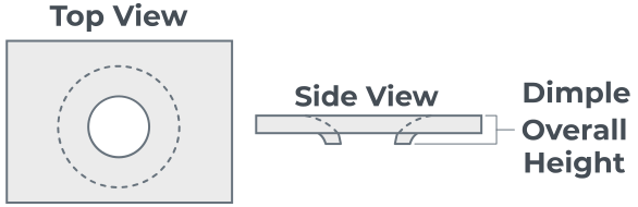
Dimple overall height (.500" dimple) .125"
Dimple overall height (.750" dimple) .127"
Dimple overall height (1.000" dimple) .170"
Dimple overall height (1.250" dimple) .183"
Dimple overall height (1.500" dimple) .200"
Dimple overall height (1.750" dimple) .208"
Dimple overall height (2.000" dimple) .225"
Dimple overall height (2.500" dimple) .285"
Dimple overall height (3.000" dimple) .365"
A1008 MILD STEEL PROPERTIES
Material Composition Iron (Fe): 99.31 – 99.7 Manganese (Mn): 0.3 – 0.5 Carbon (C): 0 – 0.1 Sulfur (S): 0 – 0.05 Phosphorus (P): 0 – 0.04
Density 490 lb/ft^3
Heat treatments process N/A
ASTM A1008-21A-CS-TYPE-B
Tensile Strength (Ultimate) 54 ksi
Tensile Strength (Yield) 45 ksi
Shear Strength 34 ksi
Shear Modulus 11000 ksi
Fatigue Strength 32 ksi
Brinell Hardness 100
Elongation at Break 22%
Elastic Modulus 27000 ksi
Poisson’s Ratio .29
Thermal Conductivity 43 BTU/h-ft °F
Melting Point 2600 °F
Magnetic Yes
Does it Rust Yes

.048"1.22mm Mild Steel

Material Details & Specifications

A1008 Mild Steel 0.048" GENERAL DETAILS
Advertised Thickness 0.048"
Gauge 18
Thickness tolerance positive 0.005"
Thickness tolerance negative 0.004"
Mill Finish Cold Rolled
Top/Bottom finish Identical both sides
Sourced from Global
LASER CUTTING SPECIFICATIONS
Cutting process Fiber laser
Cut tolerance +/- 0.005"
Flatness tolerance before cutting +/-0.030 per foot
Min part size .25″ x .375″
Max part size 44″ x 30″
Min hole size .018″
Min bridge size .024″
Min hole to edge distance .020″
Tab and slot tolerance .010"
A1008 Mild Steel 0.048" GENERAL DETAILS
Advertised Thickness 0.048"
Gauge 18
Thickness tolerance positive 0.005"
Thickness tolerance negative 0.004"
Mill Finish Cold Rolled
Top/Bottom finish Identical both sides
Sourced from Global
LASER CUTTING SPECIFICATIONS
Cutting process Fiber laser
Cut tolerance +/- 0.005"
Flatness tolerance before cutting +/-0.030 per foot
Min part size .25″ x .375″
Max part size 44″ x 30″
Min hole size .018″
Min bridge size .024″
Min hole to edge distance .020″
Tab and slot tolerance .010"
BENDING SPECIFICATIONS
Min bend part size .375" x 1.5"
Max bending flat part size 44" x 30"
Max bend length 44"
Min flange length (before bend/Flat Pattern) 90° or less (obtuse) 0.255"
Min flange length (after bend) 90° or less (obtuse) 0.298"
Minimum Length Center of bend line 91-130* (Acute) 0.344"
Die width 0.472"
Effective bend radius @ 90° 0.045"
Max bend angle 130°
Bend angle tolerance (bend length up to 24″) +/- 1 degree
Bend angle tolerance (bend length over 24″) +/- 2 degrees
Bend deduction @ 90° 0.086"
K Factor 0.38
Bend relief depth 0.113"
Minimum joggle. Bend line to bend line @90° max flange 0.308"
Maximum joggle. Bend line to bend line @90° max flange 3.750"
DEBURRING SPECIFICATIONS
Min deburring part size 1" x 3"
Max deburring part size 36″ x 46″
DIMPLE SPECIFICATIONS
Min dimple part size 1.200" x 5.200"
Max dimple part size 26" x 56"
Smallest dimple .500"
Largest dimple 3.000"
Dimple overall height (.500" dimple) .140"
Dimple overall height (.750" dimple) .150"
Dimple overall height (1.000" dimple) .190"
Dimple overall height (1.250" dimple) .200"
Dimple overall height (1.500" dimple) .220"
Dimple overall height (1.750" dimple) .235"
Dimple overall height (2.000" dimple) .250"
Dimple overall height (2.500" dimple) .270"
Dimple overall height (3.000" dimple) .385"
HARDWARE SPECIFICATIONS
Min hardware part size 1″ x 1.5″
Max hardware part size 36″ x 46″
Max 4 sided box flange height (hardware 3"
Hardware specific specifications Please view our Hardware Catalog
PLATING SPECIFICATIONS
Min Plating Part Size 1″ x 3″
Max Plating Part Size 23″ x 23″
POWDER COATING SPECIFICATIONS
Min powder coating part size 1" x 3"
Max powder coating part size 30" x 36"
A1008 MILD STEEL PROPERTIES
Material Composition Iron (Fe): 99.31 – 99.7 Manganese (Mn): 0.3 – 0.5 Carbon (C): 0 – 0.1 Sulfur (S): 0 – 0.05 Phosphorus (P): 0 – 0.04
Density 490 lb/ft^3
Heat treatments process N/A
ASTM A1008-21A-CS-TYPE-B
Tensile Strength (Ultimate) 54 ksi
Tensile Strength (Yield) 45 ksi
Shear Strength 34 ksi
Shear Modulus 11000 ksi
Fatigue Strength 32 ksi
Brinell Hardness 100
Elongation at Break 22%
Elastic Modulus 27000 ksi
Poisson’s Ratio .29
Thermal Conductivity 43 BTU/h-ft °F
Melting Point 2600 °F
Magnetic Yes
Does it Rust Yes

.059"1.50mm Mild Steel

Material Details & Specifications

A1008 Mild Steel 0.059" GENERAL DETAILS
Advertised Thickness 0.059"
Gauge 16
Thickness tolerance positive 0.006"
Thickness tolerance negative 0.004"
Mill Finish Cold Rolled
Top/Bottom finish Identical both sides
Sourced from Global
LASER CUTTING SPECIFICATIONS
Cutting process Fiber laser
Cut tolerance +/- 0.005"
Flatness tolerance before cutting +/-0.030 per foot
Min part size .25″ x .375″
Max part size 44″ x 30″
Recommended Min hole size .022″
Min hole size .014"
Min bridge size .030″
Min hole to edge distance .020″
Tab and slot tolerance .010"
BENDING SPECIFICATIONS
Min bend part size .375" x 1.5"
Max bending flat part size 44" x 30"
Max bend length 44"
Min flange length (before bend/Flat Pattern) 90° or less (obtuse) 0.255"
Min flange length (after bend) 90° or less (obtuse) 0.309"
Minimum Length Center of bend line 91-130* (Acute) .344
Die width 0.472"
Effective bend radius @ 90° 0.063"
Max bend angle 130°
Bend angle tolerance (bend length up to 24″) +/- 1 degree
Bend angle tolerance (bend length over 24″) +/- 2 degrees
Bend deduction @ 90° 0.108"
K Factor 0.40
Bend relief depth 0.142
Minimum joggle. Bend line to bend line @90° max flange 0.320"
Maximum joggle. Bend line to bend line @90° max flange 3.750"
DEBURRING SPECIFICATIONS
Min deburring part size 1" x 3"
Max deburring part size 36″ x 46″
DIMPLE SPECIFICATIONS
Min dimple part size 1.200" x 5.200"
Max dimple part size 26" x 56"
Smallest dimple .500"
Largest dimple 3.000"
Dimple overall height (.500" dimple) .151"
Dimple overall height (.750" dimple) .155"
Dimple overall height (1.000" dimple) .200"
Dimple overall height (1.250" dimple) .215"
Dimple overall height (1.500" dimple) .230"
Dimple overall height (1.750" dimple) .248"
Dimple overall height (2.000" dimple) .260"
Dimple overall height (2.500" dimple) .315"
Dimple overall height (3.000" dimple) .400"
HARDWARE SPECIFICATIONS
Min hardware part size 1″ x 1.5″
Max hardware part size 36″ x 46″
Max 4 sided box flange height (hardware 3"
Hardware specific specifications Please view our Hardware Catalog
PLATING SPECIFICATIONS
Min Plating Part Size 1″ x 3″
Max Plating Part Size 23″ x 23″
POWDER COATING SPECIFICATIONS
Min powder coating part size 1" x 3"
Max powder coating part size 30" x 36"
TAPPING SPECIFICATIONS
Largest Tap M3 x 0.5
Smallest Tap M2 x 0.4
Min Flat Part Size Tapping 0.949" x 1.5"
Max Flat Part Size Tapping 36" x 46"
Tapping Min Hole to Edge 0.020"
Tapping Min Hole Center to Material Edge Tap hole size/2 +0.020"
A1008 MILD STEELPROPERTIES
Material Composition Iron (Fe): 99.31 – 99.7 Manganese (Mn): 0.3 – 0.5 Carbon (C): 0 – 0.1 Sulfur (S): 0 – 0.05 Phosphorus (P): 0 – 0.04
Density 490 lb/ft^3
Heat treatments process N/A
ASTM A1008-21A-CS-TYPE-B
Tensile Strength (Ultimate) 54 ksi
Tensile Strength (Yield) 45 ksi
Shear Strength 34 ksi
Shear Modulus 11000 ksi
Fatigue Strength 32 ksi
Brinell Hardness 100
Elongation at Break 22%
Elastic Modulus 27000 ksi
Poisson’s Ratio .29
Thermal Conductivity 43 BTU/h-ft °F
Melting Point 2600 °F
Magnetic Yes
Does it Rust Yes

.074"1.88mm Mild Steel

Material Details & Specifications

A1008 Mild Steel 0.074" GENERAL DETAILS
Advertised Thickness 0.074"
Gauge 14
Thickness tolerance positive 0.006"
Thickness tolerance negative 0.005"
Mill Finish Cold Rolled
Top/Bottom finish Identical both sides
Sourced from Global
LASER CUTTING SPECIFICATIONS
Cutting process Fiber laser
Cut tolerance +/- 0.005"
Flatness tolerance before cutting +/-0.030 per foot
Min part size .25″ x .375″
Max part size 44″ x 30″
Recommended Min hole size .028″
Min hole size .017"
Min bridge size .032″
Min hole to edge distance .022″
Tab and slot tolerance .010"
BENDING SPECIFICATIONS
Min bend part size .375" x 1.5"
Max bending flat part size 44" x 30"
Max bend length 44"
Min flange length (before bend/Flat Pattern) 90° or less (obtuse) 0.255"
Min flange length (after bend) 90° or less (obtuse) 0.320"
Minimum Length Center of bend line 91-130* (Acute) .344
Die width 0.472"
Effective bend radius @ 90° 0.063"
Max bend angle 130°
Bend angle tolerance (bend length up to 24″) +/- 1 degree
Bend angle tolerance (bend length over 24″) +/- 2 degrees
Bend deduction @ 90° 0.129"
K Factor 0.40
Bend relief depth 0.157"
Minimum joggle. Bend line to bend line @90° max flange 0.336"
Maximum joggle. Bend line to bend line @90° max flange 3.750"
DEBURRING SPECIFICATIONS
Min deburring part size 1" x 3"
Max deburring part size 36″ x 46″
DIMPLE SPECIFICATIONS
Min dimple part size 1.950" x 5.200"
Max dimple part size 26" x 56"
Smallest dimple 1.000"
Largest dimple 3.000"
Dimple overall height (1.000" dimple) .250"
Dimple overall height (1.250" dimple) .230"
Dimple overall height (1.500" dimple) .250"
Dimple overall height (1.750" dimple) .266"
Dimple overall height (2.000" dimple) .285"
Dimple overall height (2.500" dimple) .345"
Dimple overall height (3.000" dimple) .415"
HARDWARE SPECIFICATIONS
Min hardware part size 1″ x 1.5″
Max hardware part size 36″ x 46″
Max 4 sided box flange height (hardware 3"
Hardware specific specifications Please view our Hardware Catalog
PLATING SPECIFICATIONS
Min Plating Part Size 1″ x 3″
Max Plating Part Size 23″ x 23″
POWDER COATING SPECIFICATIONS
Min powder coating part size 1" x 3"
Max powder coating part size 30" x 36"
TAPPING SPECIFICATIONS
Largest Tap M6 x 1.0
Smallest Tap M2 x 0.4
Min Flat Part Size Tapping 0.949" x 1.5"
Max Flat Part Size Tapping 36" x 46"
Tapping Min Hole to Edge 0.022"
Tapping Min Hole Center to Material Edge Tap hole size/2 +0.022"
A1008 MILD STEEL PROPERTIES
Material Composition Iron (Fe): 99.31 – 99.7 Manganese (Mn): 0.3 – 0.5 Carbon (C): 0 – 0.1 Sulfur (S): 0 – 0.05 Phosphorus (P): 0 – 0.04
Density 490 lb/ft^3
Heat treatments process N/A
ASTM A1008-21A-CS-TYPE-B
Tensile Strength (Ultimate) 54 ksi
Tensile Strength (Yield) 45 ksi
Shear Strength 34 ksi
Shear Modulus 11000 ksi
Fatigue Strength 32 ksi
Brinell Hardness 100
Elongation at Break 12%
Elastic Modulus 27000 ksi
Poisson’s Ratio .29
Thermal Conductivity 43 BTU/h-ft °F
Melting Point 2600°F
Magnetic Yes
Does it Rust Yes

.104"2.64mm Mild Steel

Material Details & Specifications

A1008 Mild Steel 0.104" GENERAL DETAILS
Advertised Thickness 0.104"
Gauge 12
Thickness tolerance positive 0.007"
Thickness tolerance negative 0.006"
Mill Finish Cold Rolled
Top/Bottom finish Identical both sides
Sourced from USA/Global
LASER CUTTING SPECIFICATIONS
Cutting process Fiber laser
Cut tolerance +/- 0.005"
Flatness tolerance before cutting +/-0.030 per foot
Min part size .25″ x .375″
Max part size 44″ x 30″
Recommended Min hole size .040″
Min hole size .023"
Min bridge size .035″
Min hole to edge distance .031″
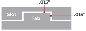
Tab and slot tolerance .015"
BENDING SPECIFICATIONS
Min bend part size .375" x 1.5"
Max bending flat part size 44" x 30"
Max bend length 44"
Min flange length (before bend/Flat Pattern) 90° or less (obtuse) 0.368"
Min flange length (after bend) 90° or less (obtuse) 0.459"
Minimum Length Center of bend line 91-130* (Acute) .497"
Die width 0.630"
Effective bend radius @ 90° 0.063"
Min bend anlge 5°
Max bend angle 130°
Bend angle tolerance (bend length up to 24″) +/- 1 degree
Bend angle tolerance (bend length over 24″) +/- 2 degrees
Bend deduction @ 90° 0.181"
K Factor 0.34
Bend relief depth 0.187"
Minimum joggle. Bend line to bend line @90° max flange 0.482"
Maximum joggle. Bend line to bend line @90° max flange 3.750"
DEBURRING SPECIFICATIONS
Min deburring part size 1" x 3"
Max deburring part size 36″ x 46″
DIMPLE SPECIFICATIONS
Min dimple part size 2.450" x 5.200"
Max dimple part size 26" x 56"
Smallest dimple 1.250"
Largest dimple 3.000"
Dimple overall height (1.250" dimple) .265"
Dimple overall height (1.500" dimple) .276"
Dimple overall height (1.750" dimple) .305"
Dimple overall height (2.000" dimple) .315"
Dimple overall height (2.500" dimple) .375"
Dimple overall height (3.000" dimple) .455"
HARDWARE SPECIFICATIONS
Min hardware part size 1″ x 1.5″
Max hardware part size 36″ x 46″
Max 4 sided box flange height (hardware 3"
Hardware specific specifications Please view our Hardware Catalog
PLATING SPECIFICATIONS
Min Plating Part Size 1″ x 3″
Max Plating Part Size 23″ x 23″
POWDER COATING SPECIFICATIONS
Min powder coating part size 1" x 3"
Max powder coating part size 30" x 36"
TAPPING SPECIFICATIONS
Largest Tap 1/4-28
Smallest Tap M2 x 0.4
Min Flat Part Size Tapping 0.949" x 1.5"
Max Flat Part Size Tapping 36" x 36"
Tapping Min Hole to Edge 0.031"
Tapping Min Hole Center to Material Edge Tap hole size/2 +0.031"
A1008 MILD STEEL PROPERTIES
Material Composition Iron (Fe): 99.31 – 99.7 Manganese (Mn): 0.3 – 0.5 Carbon (C): 0 – 0.1 Sulfur (S): 0 – 0.05 Phosphorus (P): 0 – 0.04
Density 490 lb/ft^3
Heat treatments process N/A
ASTM A1008-21A-CS-TYPE-B
Tensile Strength (Ultimate) 54 ksi
Tensile Strength (Yield) 45 ksi
Shear Strength 34 ksi
Shear Modulus 11000 ksi
Fatigue Strength 32 ksi
Brinell Hardness 100
Elongation at Break 22%
Elastic Modulus 27000 ksi
Poisson’s Ratio .29
Thermal Conductivity 43 BTU/h-ft °F
Melting Point 2600 °F
Magnetic Yes
Does it Rust Yes


.119"3.02mm Mild Steel

Material Details & Specifications

A1008 Mild Steel 0.119" GENERAL DETAILS
Advertised Thickness 0.119"
Gauge 11
Thickness tolerance positive 0.007"
Thickness tolerance negative 0.006"
Mill Finish Cold Rolled
Top/Bottom finish Identical both sides
Sourced from USA/Global
LASER CUTTING SPECIFICATIONS
Cutting process Fiber laser
Cut tolerance +/- 0.005"
Flatness tolerance before cutting +/-0.030 per foot
Min part size .25″ x .375″
Max part size 44″ x 30″
Recommended Min hole size .040″
Min hole size .028"
Min bridge size .035″
Min hole to edge distance .036″
Tab and slot tolerance .015"
BENDING SPECIFICATIONS
Min bend part size .375" x 1.5"
Max bending flat part size 44" x 30"
Max bend length 44"
Min flange length (before bend/Flat Pattern) 90° or less (obtuse) 0.368"
Min flange length (after bend) 90° or less (obtuse) 0.466"
Minimum Length Center of bend line 91-130* (Acute) 0.497"
Die width 0.630"
Effective bend radius @ 90° 0.063"
Max bend angle 130°
Bend angle tolerance (bend length up to 24″) +/- 1 degree
Bend angle tolerance (bend length over 24″) +/- 2 degrees
Bend deduction @ 90° 0.196"
K Factor 0.38
Bend relief depth 0.202"
Minimum joggle. Bend line to bend line @90° max flange 0.499"
Maximum joggle. Bend line to bend line @90° max flange 3.750"
DEBURRING SPECIFICATIONS
Min deburring part size 1" x 3"
Max deburring part size 36″ x 46″
DIMPLE SPECIFICATIONS
Min dimple part size 2.450" x 5.200"
Max dimple part size 26" x 56"
Smallest dimple 1.250"
Largest dimple 3.000"
Dimple overall height (1.250" dimple) .270"
Dimple overall height (1.500" dimple) .285"
Dimple overall height (1.750" dimple) .310"
Dimple overall height (2.000" dimple) .328"
Dimple overall height (2.500" dimple) .390"
Dimple overall height (3.000" dimple) .470"
HARDWARE SPECIFICATIONS
Min hardware part size 1″ x 1.5″
Max hardware part size 36″ x 46″
Max 4 sided box flange height (hardware 3"
Hardware specific specifications Please view our Hardware Catalog
PLATING SPECIFICATIONS
Min Plating Part Size 1″ x 3″
Max Plating Part Size 23″ x 23″
POWDER COATING SPECIFICATIONS
Min powder coating part size 1" x 3"
Max powder coating part size 30" x 36"
TAPPING SPECIFICATIONS
Largest Tap 5/16-24
Smallest Tap M2 x 0.4
Min Flat Part Size Tapping 0.949" x 1.5"
Max Flat Part Size Tapping 36" x 46"
Tapping Min Hole to Edge 0.036"
Tapping Min Hole Center to Material Edge Tap hole size/2 +0.036"
TUMBLE SPECIFICATIONS
Min Part Size Tumbling 0.5″ x 1.5″
Max Part Size Tumbling 4″ x 7″
A1008 MILD STEEL PROPERTIES
Material Composition Iron (Fe): 99.31 – 99.7 Manganese (Mn): 0.3 – 0.5 Carbon (C): 0 – 0.1 Sulfur (S): 0 – 0.05 Phosphorus (P): 0 – 0.04
Density 490 lb/ft^3
Heat treatments process N/A
ASTM A1008-21A-CS-TYPE-B
Tensile Strength (Ultimate) 54 ksi
Tensile Strength (Yield) 45 ksi
Shear Strength 34 ksi
Shear Modulus 11000 ksi
Fatigue Strength 32 ksi
Brinell Hardness 100
Elongation at Break 22%
Elastic Modulus 27000 ksi
Poisson’s Ratio .29
Thermal Conductivity 43 BTU/h-ft °F
Melting Point 2600 °F
Magnetic Yes
Does it Rust Yes

.135"3.43mm Mild Steel

Material Details & Specifications

A1008 Mild Steel 0.135" GENERAL DETAILS
Advertised Thickness 0.135"
Gauge 10
Thickness tolerance positive 0.006"
Thickness tolerance negative 0.006"
Mill Finish Cold Rolled
Top/Bottom finish Identical both sides
Sourced from USA/Global
LASER CUTTING SPECIFICATIONS
Cutting process Fiber laser
Cut tolerance +/- 0.005"
Flatness tolerance before cutting +/-0.030 per foot
Min part size .25″ x .375″
Max part size 44″ x 30″
Recommended Min hole size .051″
Min hole size .032"
Min bridge size .055″
Min hole to edge distance .041″
Tab and slot tolerance .010"
BENDING SPECIFICATIONS
Min bend part size .375" x 1.5"
Max bending flat part size 44" x 30"
Max bend length 44"
Min flange length (before bend/Flat Pattern) 90° or less (obtuse) 0.620"
Min flange length (after bend) 90° or less (obtuse) 0.742"
Minimum Length Center of bend line 91-130* (Acute) 0.837"
Die width 0.984"
Effective bend radius @ 90° 0.100"
Max bend angle 110°
Minimum bend angle 5°
Bend angle tolerance (bend length up to 24″) +/- 1 degree
Bend angle tolerance (bend length over 24″) +/- 2 degrees
Bend deduction @ 90° 0.244"
K Factor 0.32
Bend relief depth 0.255"
Minimum joggle. Bend line to bend line @90° max flange 0.769"
Maximum joggle. Bend line to bend line @90° max flange 3.750"
DEBURRING SPECIFICATIONS
Min deburring part size 1" x 3"
Max deburring part size 36″ x 46″
HARDWARE SPECIFICATIONS
Min hardware part size 1″ x 1.5″
Max hardware part size 36″ x 46″
Minimum distance from center of bend to center of hardware insertion hole (measured from flat pattern) .488″
Max 4 sided box flange height (hardware 3"
Hardware specific specifications Please view our Hardware Catalog
PLATING SPECIFICATIONS
Min Plating Part Size 1″ x 3″
Max Plating Part Size 23″ x 23″
POWDER COATING SPECIFICATIONS
Min powder coating part size 1" x 3"
Max powder coating part size 30" x 36"
TAPPING SPECIFICATIONS
Largest Tap M10 x 1.5
Smallest Tap M2 x 0.4
Min Flat Part Size Tapping 0.949" x 1.5"
Max Flat Part Size Tapping 36" x 46"
Tapping Min Hole to Edge 0.041"
Tapping Min Hole Center to Material Edge Tap hole size/2 +0.041"
TUMBLE SPECIFICATIONS
Min Part Size Tumbling 0.5″ x 1.5″
Max Part Size Tumbling 4″ x 7″
A1008 MILD STEEL PROPERTIES
Material Composition Iron (Fe): 99.31 – 99.7 Manganese (Mn): 0.3 – 0.5 Carbon (C): 0 – 0.1 Sulfur (S): 0 – 0.05 Phosphorus (P): 0 – 0.04
Density 490 lb/ft^3
Heat treatments process N/A
ASTM A1008-21A-CS-TYPE-B
Tensile Strength (Ultimate) 54 ksi
Tensile Strength (Yield) 45 ksi
Shear Strength 34 ksi
Shear Modulus 11000 ksi
Fatigue Strength 32 ksi
Brinell Hardness 100
Elongation at Break 22%
Elastic Modulus 27000 ksi
Poisson’s Ratio .29
Thermal Conductivity 43 BTU/h-ft °F
Melting Point 2600 °F
Magnetic Yes
Does it Rust Yes

.187"4.75mm Mild Steel

Material Details & Specifications

A36 HRPO 0.187" General Details
Advertised Thickness 0.187"
Gauge N/A
Thickness tolerance positive 0.015"
Thickness tolerance negative 0.015"
Mill Finish Hot Rolled Pickled and Oiled
Steel Type HRP&O (typically dual certified ASTM A1018 CS Type B / for conversion to ASTM A36)
Top/Bottom finish Identical both sides
Sourced from USA/Global


LASER CUTTING SPECIFICATIONS
Cutting process Fiber laser
Cut tolerance +/- 0.005"
Flatness tolerance before cutting +/-0.030 per foot
Min part size .5″ x .570″
Max part size 44″ x 30″
Recommended Min hole size .070″
Min hole size .042"
Min bridge size .073″
Min hole to edge distance .056″
Tab and slot tolerance .015"


BENDING SPECIFICATIONS
Min bend part size .375" x 1.5"
Max bending flat part size 44" x 30"
Max bend length 44"
Min flange length (before bend/Flat Pattern) 90° or less (obtuse) 0.620"
Min flange length (after bend) 90° or less (obtuse) 0.781"
Min length center of bend line 91-130* (Acute) N/A
Die width 0.984"
Effective bend radius @ 90° 0.125"
Max bend angle 90°
Bend angle tolerance (bend length up to 24″) +/- 1 degree
Bend angle tolerance (bend length over 24″) +/- 2 degrees
Bend deduction @ 90° 0.323"
K Factor 0.36
Bend relief depth 0.332"
Minimum joggle. Bend line to bend line @90° max flange 0.826"
Maximum joggle. Bend line to bend line @90° max flange 3.750"
DEBURRING SPECIFICATIONS
Min deburring part size 1" x 3"
Max deburring part size 36″ x 46″
HARDWARE SPECIFICATIONS
Min hardware part size 1″ x 1.5″
Max hardware part size 36″ x 46″
Max 4 sided box flange height (hardware 3"
Hardware specific specifications Please view our Hardware Catalog
PLATING SPECIFICATIONS
Min Plating Part Size 1″ x 3″
Max Plating Part Size 23″ x 23″
POWDER COATING SPECIFICATIONS
Min powder coating part size 1" x 3"
Max powder coating part size 30" x 36"
TAPPING SPECIFICATIONS
Largest Tap 1/2-20
Smallest Tap 2-56
Min Flat Part Size Tapping 0.949" x 1.5"
Max Flat Part Size Tapping 36" x 46"
Tapping Min Hole to Edge 0.056"
Tapping Min Hole Center to Material Edge Tap hole size/2 +0.056"
TUMBLE SPECIFICATIONS
Min Part Size Tumbling 0.5″ x 1.5″
Max Part Size Tumbling 4″ x 7″
A36 HRPO PROPERTIES
Material Composition Iron (Fe): 98.0 Manganese (Mn): 1.03 Carbon (C): 0.25 – 0.290 Copper (Cu): 0.20 Sulfur (S): .050 Phosphorus (P): 0.04 Silicon (Si): 0.280
Density 490 lb/ft^3
Heat treatments process N/A
ASTM A1011-18A-CS-TYPE B
Tensile Strength (Ultimate) 69 ksi
Tensile Strength (Yield) 41 ksi
Shear Strength 44 ksi
Shear Modulus 11000 ksi
Fatigue Strength 29 ksi
Brinell Hardness 140
Elongation at Break 22%
Elastic Modulus 27000 ksi
Poisson’s Ratio .29
Thermal Conductivity 43 BTU/h-ft °F
Melting Point 2600 °F
Magnetic Yes
Does it Rust Yes


.250"6.35mm Mild Steel

Material Details & Specifications

A36 HRPO 0.250" General Details
Advertised Thickness 0.250"
Gauge N/A
Thickness tolerance positive 0.015"
Thickness tolerance negative 0.015"
Mill Finish Hot Rolled Pickled and Oiled
Steel Type HRP&O (typically dual certified ASTM A1018 CS Type B / for conversion to ASTM A36)
Top/Bottom finish Identical both sides
Sourced from USA/Global
LASER CUTTING SPECIFICATIONS
Cutting process Fiber laser
Cut tolerance +/- 0.005"
Flatness tolerance before cutting +/-0.030 per foot
Min part size .500″ x .750″
Max part size 44″ x 30″
Recommended Min hole size .095″
Min hole size .057"
Min bridge size .125″
Min hole to edge distance .075″
Tab and slot tolerance .015"
BENDING SPECIFICATIONS
Min bend part size .375" x 1.5"
Max bending flat part size 44" x 30"
Max bend length 42"
Min flange length (before bend/Flat Pattern) 90° or less (obtuse) 1.150"
Min flange length (after bend) 90° or less (obtuse) 1.361"
Min length center of bend line 91-130* (Acute) N/A
Die width 1.575"
Effective bend radius @ 90° 0.150"
Max bend angle 90°
Bend angle tolerance (bend length up to 24″) +/- 1 degree
Bend angle tolerance (bend length over 24″) +/- 2 degrees
Bend deduction @ 90° 0.422"
K Factor 0.36
Bend relief depth 0.420"
Minimum joggle. Bend line to bend line @90° max flange 1.425"
Maximum joggle. Bend line to bend line @90° max flange 3.750"
DEBURRING SPECIFICATIONS
Min deburring part size 1" x 3"
Max deburring part size 36″ x 46″
HARDWARE SPECIFICATIONS
Min hardware part size 1″ x 1.5″
Max hardware part size 36″ x 46″
Max 4 sided box flange height (hardware 3"
Hardware specific specifications Please view our Hardware Catalog
PLATING SPECIFICATIONS
Min Plating Part Size 1″ x 3″
Max Plating Part Size 23″ x 23″
POWDER COATING SPECIFICATIONS
Min powder coating part size 1" x 3"
Max powder coating part size 30" x 36"
TAPPING SPECIFICATIONS
Largest Tap 1/2-20
Smallest Tap M2.5 x 0.45
Min Flat Part Size Tapping 0.949" x 1.5"
Max Flat Part Size Tapping 36" x 46"
Tapping Min Hole to Edge 0.075"
Tapping Min Hole Center to Material Edge Tap hole size/2 +0.075"
TUMBLE SPECIFICATIONS
Min Part Size Tumbling 0.5″ x 1.5″
Max Part Size Tumbling 4″ x 7″
A36 HRPO PROPERTIES
Material Composition Iron (Fe): 98.0 Manganese (Mn): 1.03 Carbon (C): 0.25 – 0.290 Copper (Cu): 0.20 Sulfur (S): .050 Phosphorus (P): 0.04 Silicon (Si): 0.280
Density 490 lb/ft^3
Heat treatments process N/A
ASTM A1011-18A-CS-TYPE B
Tensile Strength (Ultimate) 69 ksi
Tensile Strength (Yield) 41 ksi
Shear Strength 44 ksi
Shear Modulus 11000 ksi
Fatigue Strength 29 ksi
Brinell Hardness 140
Elongation at Break 22%
Elastic Modulus 27000 ksi
Poisson’s Ratio .29
Thermal Conductivity 43 BTU/h-ft °F
Melting Point 2600 °F
Magnetic Yes
Does it Rust Yes

.313"8.0mm Mild Steel

Material Details & Specifications

A36 HRP 0.313" General Details
Advertised Thickness 0.313"
Gauge N/A
Thickness tolerance positive 0.040"
Thickness tolerance negative 0.040"
Mill Finish Hot Rolled Pickled & Oiled (HRP&O)
Top/Bottom finish Identical both sides
Sourced from USA/Global
LASER CUTTING SPECIFICATIONS
Cutting process Fiber laser
Cut tolerance +/- 0.005"
Flatness tolerance before cutting +/-0.030 per foot
Min part size 1.00″ x 1.00″
Max part size 44″ x 30″
Recommended Min hole size .118″
Min hole size .075"
Min bridge size .118″
Min hole to edge distance .094″
Tab and slot tolerance .050"
DEBURRING SPECIFICATIONS
Min deburring part size 1" x 3"
Max deburring part size 24″ x 35″
A36 HRP 0.313" General Details
Advertised Thickness 0.313"
Gauge N/A
Thickness tolerance positive 0.040"
Thickness tolerance negative 0.040"
Mill Finish Hot Rolled Pickled & Oiled (HRP&O)
Top/Bottom finish Identical both sides
Sourced from USA/Global
LASER CUTTING SPECIFICATIONS
Cutting process Fiber laser
Cut tolerance +/- 0.005"
Flatness tolerance before cutting +/-0.030 per foot
Min part size 1.00″ x 1.00″
Max part size 44″ x 30″
Recommended Min hole size .118″
Min hole size .075"
Min bridge size .118″
Min hole to edge distance .094″
Tab and slot tolerance .050"
DEBURRING SPECIFICATIONS
Min deburring part size 1" x 3"
Max deburring part size 24″ x 35″
HARDWARE SPECIFICATIONS
Min hardware part size 1″ x 1.5″
Max hardware part size 36″ x 46″
Max 4 sided box flange height (hardware N/A
Hardware specific specifications Please view our Hardware Catalo
PLATING SPECIFICATIONS
Min Plating Part Size 1″ x 3″
Max Plating Part Size 23″ x 23″
POWDER COATING SPECIFICATIONS
Min powder coating part size 1" x 3"
Max powder coating part size 30" x 36"
TAPPING SPECIFICATIONS
Largest Tap 1/2-20
Smallest Tap M4 x 0.7
Min Flat Part Size Tapping 0.949" x 1.5"
Max Flat Part Size Tapping 36" x 46"
Tapping Min Hole to Edge 0.094"
Tapping Min Hole Center to Material Edge Tap hole size/2 +0.094"
TUMBLE SPECIFICATIONS
Min Part Size Tumbling 0.5″ x 1.5″
Max Part Size Tumbling 4″ x 7″
A36 HRP PROPERTIES
Material Composition Iron (Fe): Balance (~98.7–99.0) Manganese (Mn): 0.86 Carbon (C): 0.06 Copper (Cu): 0.12 Sulfur (S): 0.002 Phosphorus (P): 0.009 Silicon (Si): 0.03 Chromium (Cr): 0.05 Nickel (Ni): 0.07 Aluminum (Al): 0.031 Columbium/Niobium (Cb/Nb): 0.017
Density 490 lb/ft^3
Heat treatments process N/A
ASTM ASTM A36
Tensile Strength (Ultimate) 72.9 ksi
Tensile Strength (Yield) 65 ksi
Shear Strength 45 ksi
Shear Modulus 11000 ksi
Fatigue Strength 29 ksi
Brinell Hardness 140
Elongation at Break 31%
Elastic Modulus 27000 ksi
Poisson’s Ratio .29
Thermal Conductivity 43 BTU/h-ft °F
Melting Point 2600 °F
Magnetic Yes
Does it Rust Yes

.375"9.5mm Mild Steel

Material Details & Specifications

A36 HRP 0.375" General Details
Advertised Thickness 0.375"
Gauge N/A
Thickness tolerance positive 0.040"
Thickness tolerance negative 0.040"
Mill Finish Hot Rolled Pickled & Oiled (HRP&O)
Top/Bottom finish Identical both sides
Sourced from USA/Global
LASER CUTTING SPECIFICATIONS
Cutting process Fiber laser
Cut tolerance +/- 0.005"
Flatness tolerance before cutting +/-0.030 per foot
Min part size 1.00″ x 1.00″
Max part size 44″ x 30″
Recommended Min hole size .188″
Min hole size .085"
Min bridge size .160″
Min hole to edge distance .113″
Tab and slot tolerance .050"
DEBURRING SPECIFICATIONS
Min deburring part size 1" x 3"
Max deburring part size 24″ x 29″
HARDWARE SPECIFICATIONS
Min hardware part size 1″ x 1.5″
Max hardware part size 36″ x 46″
Max 4 sided box flange height (hardware N/A
Hardware specific specifications Please view our Hardware Catalog
PLATING SPECIFICATIONS
Min Plating Part Size 1″ x 3″
Max Plating Part Size 30" x 36"
POWDER COATING SPECIFICATIONS
Min powder coating part size 1" x 3"
Max powder coating part size 23" x 23"
TAPPING SPECIFICATIONS
Largest Tap 1/2-20
Smallest Tap M6 x 1.0
Min Flat Part Size Tapping 0.949" x 1.5"
Max Flat Part Size Tapping 36" x 46"
Tapping Min Hole to Edge 0.113"
Tapping Min Hole Center to Material Edge Tap hole size/2 +0.113"
TUMBLE SPECIFICATIONS
Min Part Size Tumbling 0.5″ x 1.5″
Max Part Size Tumbling 4″ x 7″
A36 HRP PROPERTIES
Material Composition Iron (Fe): Balance (~98.7–99.0) Manganese (Mn): 0.86 Carbon (C): 0.06 Copper (Cu): 0.12 Sulfur (S): 0.002 Phosphorus (P): 0.009 Silicon (Si): 0.03 Chromium (Cr): 0.05 Nickel (Ni): 0.07 Aluminum (Al): 0.031 Columbium/Niobium (Cb/Nb): 0.017
Density 490 lb/ft^3
Heat treatments process N/A
ASTM ASTM A36
Tensile Strength (Ultimate) 72.9 ksi
Tensile Strength (Yield) 65 ksi
Shear Strength 45 ksi
Shear Modulus 11000 ksi
Fatigue Strength 29 ksi
Brinell Hardness 140
Elongation at Break 31%
Elastic Modulus 27000 ksi
Poisson’s Ratio .29
Thermal Conductivity 43 BTU/h-ft °F
Melting Point 2600 °F
Magnetic Yes
Does it Rust Yes

.500"12.7mm Mild Steel

Material Details & Specifications

A36 HRP 0.500" General Details
Advertised Thickness 0.500"
Gauge N/A
Thickness tolerance positive 0.050"
Thickness tolerance negative 0.050"
Mill Finish Hot Rolled Pickled & Oiled (HRP&O)
Top/Bottom finish Identical both sides
Sourced from USA/Global
LASER CUTTING SPECIFICATIONS
Cutting process Fiber laser
Cut tolerance +/- 0.005"
Flatness tolerance before cutting +/-0.030 per foot
Min part size 1.00″ x 1.00″
Max part size 44″ x 30″
Recommended Min hole size .190″
Min hole size .125"
Min bridge size .170″
Min hole to edge distance .150″
Tab and slot tolerance .055"
DEBURRING SPECIFICATIONS
Min deburring part size 1" x 3"
Max deburring part size 24″ x 22″
HARDWARE SPECIFICATIONS
Min hardware part size 1″ x 1.5″
Max hardware part size 36″ x 46″
Max 4 sided box flange height (hardware N/A
Hardware specific specifications Please view our Hardware Catalog
PLATING SPECIFICATIONS
Min Plating Part Size 1″ x 3″
Max Plating Part Size 23″ x 23″
POWDER COATING SPECIFICATIONS
Min powder coating part size 1" x 3"
Max powder coating part size 30" x 36"
TAPPING SPECIFICATIONS
Largest Tap 1/2-20
Smallest Tap M6 x 1.0
Min Flat Part Size Tapping 0.949" x 1.5"
Max Flat Part Size Tapping 36" x 46"
Tapping Min Hole to Edge 0.150"
Tapping Min Hole Center to Material Edge Tap hole size/2 +0.150"
TUMBLE SPECIFICATIONS
Min Part Size Tumbling 0.5″ x 1.5″
Max Part Size Tumbling 4″ x 7″


A36 HRP PROPERTIES
Material Composition Iron (Fe): Balance (~98.7–99.0) Manganese (Mn): 0.86 Carbon (C): 0.06 Copper (Cu): 0.12 Sulfur (S): 0.002 Phosphorus (P): 0.009 Silicon (Si): 0.03 Chromium (Cr): 0.05 Nickel (Ni): 0.07 Aluminum (Al): 0.031 Columbium/Niobium (Cb/Nb): 0.017
Density 490 lb/ft^3
Heat treatments process N/A
ASTM ASTM A36
Tensile Strength (Ultimate) 72.9 ksi
Tensile Strength (Yield) 65 ksi
Shear Strength 45 ksi
Shear Modulus 11000 ksi
Fatigue Strength 29 ksi
Brinell Hardness 140
Elongation at Break 31%
Elastic Modulus 27000 ksi
Poisson’s Ratio .29
Thermal Conductivity 43 BTU/h-ft °F
Melting Point 2600 °F
Magnetic Yes
Does it Rust Yes


Our laser cut mild steel is guaranteed

Our laser cut mild steel is guaranteed

We guarantee awesome quality parts. If you’re not 100% happy, we’ll give you a refund or remake on the spot – no questions, no hassle.

Start your first Metal Manufacturing project today!

Upload your CAD design, or try one of our customizable part templates to get instant pricing on your custom laser cut parts. All delivered to your door in a matter of days.

Waterjet

Upload a CAD file

We accept .ai, .dxf, .dwg, .eps, .stp, and .step

Start Your Quote

Mild steel sheet metal properties and fabrication guide

Mild steel is the workhorse of sheet metal fabrication — strong, weldable, affordable, and incredibly versatile. At SendCutSend, we offer several common mild steel grades including 1008, A36, and A36/A1018, all laser cut with ±.005″ precision and available with a range of secondary services. Below, we break down the essentials of mild steel, how its grades compare, and how to design your parts for reliable performance and clean fabrication.

Key takeaways for mild steel

  • Versatile and affordable: A dependable option for brackets, enclosures, panels, and structural parts.
  • Multiple grades available:1008 for formability, A36 for strength, and A36/A1018 for balanced performance.
  • Excellent weldability and machinability: Compatible with MIG, TIG, and spot welding.
  • Laser cut precision: Clean, burr-free edges with ±.005″ tolerances and fast turnaround.
  • Full range of secondary services: SendCutSend offers bending, hardware insertion, plating, powder coating, tapping, and tumbling for complete fabrication.

What is mild steel?

Mild steel is a low-carbon steel containing roughly 0.05–0.25% carbon, offering a balance of strength, ductility, and weldability. It’s the backbone of the metal fabrication world, used in everything from automotive brackets and fixtures to furniture and machinery. Because of its low carbon content, mild steel is easy to shape, cut, and weld — making it ideal for both prototyping and production parts.

What are the properties of mild steel?

Mild steel combines strength, formability, and cost-effectiveness. Typical properties (vary by grade):

  • Density: 0.283 lb/in³ (7.83 g/cm³)
  • Tensile strength: 45–70 ksi
  • Yield strength: 25–50 ksi
  • Elongation: 20–35%

It’s strong enough for structural use yet soft enough to bend or tap easily.

What’s the difference between 1008, A36, and A36/A1018 mild steel?

Each grade of mild steel serves a slightly different purpose:

  • Cold Rolled 1008 mild steel: Very low carbon (~0.08%) for maximum formability and clean bends. Common in sheet applications and parts that will be stamped or dimple formed.
  • Hot Rolled A36 mild steel: Stronger, with higher carbon (~0.25%) for better structural integrity and weld strength. Excellent for brackets, mounts, and load-bearing parts.
  • HRP&O A36/A1018 mild steel: A blended specification with tighter thickness and surface finish tolerances — ideal for precision sheet metal components.

All three are laser cut with the same ±.005″ precision and support SendCutSend’s bending, tapping, and coating services. If you’re not sure which is right for your design, explore each material’s dedicated page in our Material Catalog.

How does mild steel compare to stainless steel or aluminum?

Mild steel offers higher strength than aluminum and better formability than stainless, but requires protective coatings for corrosion resistance.

  • Mild steel Versus aluminum: Stronger and stiffer, but heavier and less corrosion-resistant.
  • Mild steel Versus stainless steel: Easier to weld and form, but more prone to rust if left uncoated.
  • Mild steel is bBest for: General-purpose parts where cost, strength, and machinability outweigh environmental exposure.

For more comparisons, see our Metal Comparison Guides.

How does mild steel perform during laser cutting?

Mild steel laser cuts exceptionally well, producing clean edges and tight tolerances.

  • Edge quality: Smooth and square with minimal dross.
  • Tolerance: ±.005″ across all thicknesses from .030″–.500″.
  • Heat-affected zone: Minimal, with no warping or distortion under typical conditions.

Proper design for kerf and feature size ensures a perfect fit during assembly — see our Design Guidelines for details.

Can mild steel be bent or formed?

Yes, mild steel bends cleanly and consistently, especially in thinner gauges.

  • Inside bend radius = 1x material thickness or greater for most applications.
  • 1008 mild steel offers the best ductility for complex bends or dimples.
  • Avoid bending across laser-cut features to maintain structural integrity.

Check our Bending Guidelines for recommended radii and clearances by thickness.

Can mild steel be welded or joined?

Mild steel is one of the easiest metals to weld.

  • Works with MIG, TIG, or stick welding.
  • No preheat required in most thicknesses.
  • Use ER70S-6 filler for clean, strong welds.

Because it welds so predictably, it’s a go-to material for custom brackets, roll cages, and structural assemblies.

What finishing options are available for mild steel?

Since mild steel is prone to oxidation, protective coatings are highly recommended. At SendCutSend, you can choose from several finishing services:

Review SendCutSend’s services guidelines before adding additional services to your laser cut mild steel parts.

How durable is mild steel over time?

Mild steel is strong and resilient, but it will oxidize (rust) if left unprotected.

  • Indoors or painted: Long lifespan with minimal maintenance.
  • Outdoors or humid environments: Requires plating or powder coating to prevent rust.
  • Structurally, mild steel retains strength for decades when properly protected.

Protective finishes make mild steel a long-term performer for both indoor and outdoor parts.

Design tips for mild steel sheet metal

Keep strength, bendability, and coating needs in mind during design.

  • Add relief cuts near bends for accurate angles.
  • Include drainage or vent holes for coated parts.
  • Maintain standard hole sizes for tapping or hardware insertion.
  • Choose a surface finish early to avoid double handling.

For more fabrication-specific details, review our Design Guidelines.

Why choose mild steel?

Mild steel is the all-purpose backbone of fabrication — affordable, predictable, and easy to work with. Whether you need strength (A36), formability (1008), or precision (A36/A1018), SendCutSend laser cuts your parts with ±.005″ accuracy and offers bending, coating, and hardware services to deliver a ready-to-assemble product. Explore all three mild steel grades in our Material Catalog to find the right fit for your project.
KH-TAT Electronic

Tell Us Your Requirements

For more information about KH-TAT Electronic CNC Tool’s cutting tool solutions, including standard and custom carbide drills, end mills, coatings, and machining support, please feel free to contact our team.
  • Email Brian@wjwanjia.com
  • WhatsApp +86 18967883827
  • Address No. 26, Fenghuang Second Street, Yongchuan District, Chongqing (within Fenghuang Lake Industrial Park, Yongchuan Industrial Park, Chongqing)

    Room 2008, North Building, Yinzhou Chamber of Commerce Building, Yinzhou District, Ningbo City, Zhejiang Province

    Nong Bon Daeng 13, Nong Bon Daeng, Ban Bang Xian, Chon buri 20170, Thailand

This site uses cookies

We use cookies to collect information about how you use this site. We use this information to make the website work as well as possible and improve our services.more details