



Design guidelines for hardware inserted parts
Following a few basic design guidelines will help ensure your parts pass SendCutSend review.
Min & max part sizes for hardware insertion
All parts with hardware installation need to meet certain size requirements to be manufactured correctly:
| Min part size (flat) | 1″ x 1.5″ |
| Max part size (flat) | 36″ x 46″ |
| Max hole size | 4″ (holes will be automatically resized |
These are general size requirements. Check the Hardware Catalog for specifications on each hardware type before uploading your file.
Hole sizing
When you select a hole for hardware installation, we automatically resize the hole to the required size based on the hardware you choose. The required size is listed as hole size in sheet (H) in the hardware catalog for each hardware SKU.
Because mount holes will be resized, verify there’s adequate clearance to other features and edges. Measure from the center of the mount hole to the edge of adjacent cut features.
Specifications in the hardware catalog
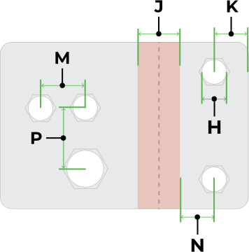
H = Hole size in sheet (+0.003″/–0.000″)
J = Bend allowance (find with Bend Calculator)
K = Minimum distance from center of hole to cut edge
N = Minimum distance from center of hole to edge of bend allowance area (J)
M = Minimum distance from hole center to hole center for two of the same hardware SKU
P = Minimum distance from hole center to hole center for two different hardware SKUs
Hardware-to-hardware distance
The minimum distance between two of the same hardware SKU is listed as spec M in the hardware catalog.
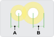
For two different hardware SKUs, calculate the minimum distance manually: the minimum distance hole C/L to edge (K) for either hardware should not overlap the hole size in sheet (H) of the other. In the example below, the shaded areas should never overlap any cut edges.
Note: Hardware that is the same size but a different type or SKU can have different specifications. For example, an 8-32 nut and an 8-32 standoff require different mount hole sizes and spacing.
Hardware-to-bend distance
Hardware holes must be far enough away from bend allowance areas to prevent interference.
- Confirm the bend allowance for your flange using the Bend Calculator (input material thickness and bend angle, find under Advanced details).
- Find the minimum distance hole C/L to edge or bend area (N) in the hardware catalog for your hardware SKU.
- Measure from the center of the hardware mount hole to the edge of the bend allowance area in your design.
You can also measure from the center of the bend to the center of the hardware hole. Calculate that minimum by adding bend allowance/2 + minimum distance hole C/L to edge or bend (N) for the hardware SKU.
No hardware on acute bends
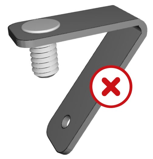
Hardware installation isn’t available on parts with acute bends. Contact support if you have questions about your design.
Hardware insertion options for sheet metal parts
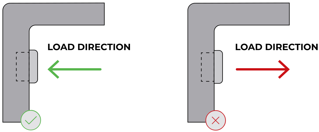
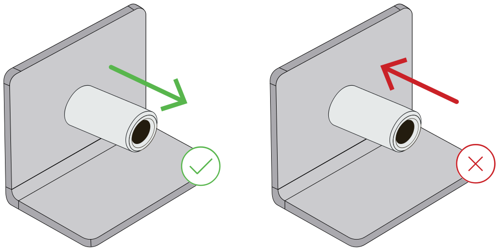
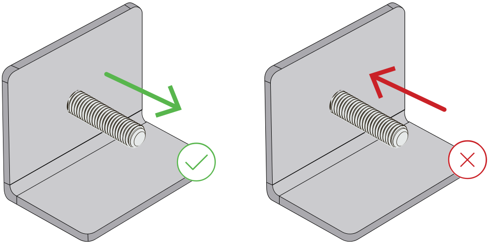
We offer three types of PEM® hardware: nuts, standoffs, and studs. Each type has a specific load direction it’s designed for, orienting hardware against the load direction can cause it to fail or pop out of the part. Use the diagrams below to confirm the correct direction for each type, then set the install face in the app.
Press fit nuts
Press fit nuts install with the load direction pulling the nut into the part, never away from it.
Press fit standoffs
Press fit standoffs install with the load direction pulling away from the part. Loading them toward the part can cause failure.
Self-clinching studs
Studs install with the threaded shaft protruding from the part. The load direction should pull along the shaft, away from the head.
Flush head standoffs and studs
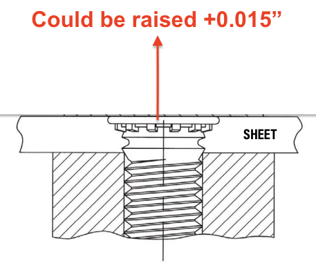
Our flush standoffs and studs are technically flush, but may be raised .015″ depending on material selection. Load direction follows the same rules as standard standoffs and studs.
What to expect with hardware inserted parts
- Visible tooling marks at the installation point
- Hardware is installed after anodizing and plating
- Hardware is installed before powder coating, hardware will be capped/plugged before coating
- Standoffs and studs may sit raised .015″ depending on material selection
- Beware scratching or marking on anodized or plated parts
- Hardware should only be used for its intended purpose, shearing, splitting, or warping may occur otherwise
- Improper use of hardware can result in failure
Additional hardware insertion resources
If you’re designing parts for hardware insertion, these resources may help:
- Hardware catalog
- Processing min/max part sizes
- Material min/max part sizes
- Drill Size Reference Chart
Pre-flight checklist
- File is in a format that we accept (2D: .dxf, .dwg, .ai, .eps; 3D: .step or .stp)
- All holes and cutouts are at least 50% material thickness for laser cut parts
- All holes and cutouts are no less than 0.070” for most waterjet cut parts
- All holes and cutouts are no less than 0.125” for all CNC routed parts
- File is built at a 1:1 scale, preferably in inch or mm units
- 2D files: all objects on the same layer, text converted to outlines, no open contours, all shapes united or merged, floating interiors bridged or stencilized
- 3D files: single solid sheet metal body, uniform thickness with a face at every edge, modeled at stock thickness with matching bend specs
- All stray points, duplicate lines, empty objects and text areas have been removed