
Design guidelines for dimple formed parts
Following a few basic design guidelines will help ensure your parts are dimple formed correctly and pass SendCutSend review.
Sizing requirements
Sizing limits apply to flat parts before bending
| Min part size (flat) | Depends on dimple selected (see chart below) |
| Max part size (flat) | 26″ x 56″ |
| Max hole size | 4.00″ – holes auto-resize to match your dimple selection |
| Dimple width positioning | 7″–19″ from edge, measured from dimple center |
Minimum part sizes based on the dimple used:
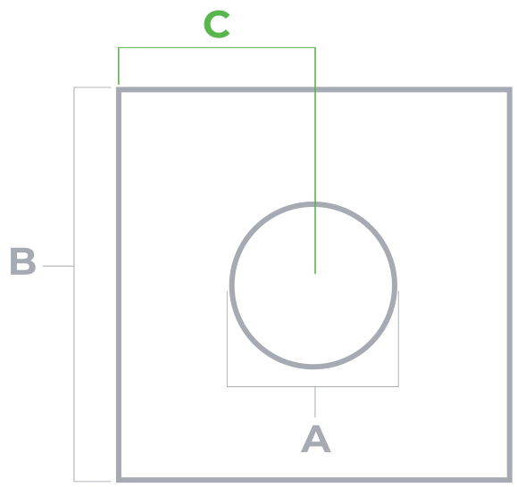
| Dimple size (A) | Min part size (B) | Min distance to edge from dimple center (C) |
|---|---|---|
| 0.500″ | 1.200″ | 0.600″ |
| 0.750” | 1.450” | 0.725″ |
| 1.000” | 1.950” | 0.975″ |
| 1.250” | 2.450” | 1.225″ |
| 1.500” | 2.700″ | 1.350″ |
| 1.750” | 3.200” | 1.800″ |
| 2.000” | 3.470” | 1.735″ |
| 2.500” | 4.450” | 2.225″ |
| 3.000” | 5.200” | 2.600″ |
Spacing & clearance
Keep dimples away from other features — holes or cutouts too close to the dimple die will deform during forming. Space dimples from bend lines by adding min feature distance (D) + half the bend allowance for your material and bend angle. Use the Bend Calculator to find your bend allowance.
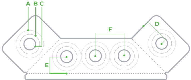
| Dimple Tool OD (A) | Dimple Major (B) | Dimple size / Minor (C)* | Min distance to other features (D) | Min distance dimple center to bend line (E) | Min distance to the same dimple (F) |
|---|---|---|---|---|---|
| 1.200″ | 0.850″ | 0.500″ | 0.600″ | 0.600″ (D) + 1/2 the bend allowance for material thickness & bend angle | 1.200″ |
| 1.450″ | 1.150” | 0.750” | 0.725” | 0.725″ (D) + 1/2 the bend allowance for material thickness & bend angle | 1.450” |
| 1.950″ | 1.575” | 1.000” | 0.975” | 0.975″ (D) + 1/2 the bend allowance for material thickness & bend angle | 1.950” |
| 2.450″ | 1.875” | 1.250” | 1.225” | 1.225″ (D) + 1/2 the bend allowance for material thickness & bend angle | 2.450” |
| 2.700″ | 2.200” | 1.500” | 1.350” | 1.350″ (D) + 1/2 the bend allowance for material thickness & bend angle | 2.700″ |
| 3.200″ | 2.500” | 1.750” | 1.600” | 1.600″ (D) + 1/2 the bend allowance for material thickness & bend angle | 3.200” |
| 3.470″ | 2.900” | 2.000” | 1.735” | 1.735″ (D) + 1/2 the bend allowance for material thickness & bend angle | 3.470” |
| 4.450″ | 3.600″ | 2.500” | 2.225” | 2.225″ (D) + 1/2 the bend allowance for material thickness & bend angle | 4.450” |
| 5.200″ | 4.375” | 3.000” | 2.600″ | 2.600″ (D) + 1/2 the bend allowance for material thickness & bend angle | 5.200” |
What to expect with dimple formed parts
- Process order: Dimple forming is performed after tapping, countersinking, deburring, and tumbling and before bending, hardware, and finishing services.
- Material behavior: Dimple forming can cause slight bowing or warping depending on material type, thickness, and geometry. Adding a bent flange can help reduce this.
- Tooling marks: Visible on all dimple formed parts and may show through finishing processes like powder coating, anodizing, or plating.
- Witness marks: May be present even after tumbling and deburring.
Feature deformation: Holes or features too close to a dimple may distort during forming. - Dimensional variation: Dimple height and minor diameter are approximate and may vary based on material and thickness.
- Finishing impact: Powder coating adds .002″–.005″ per side and may result in tighter fits around dimples.
Additional dimple forming resources
If you’re designing parts for dimple forming, these resources may help:
Pre-flight checklist
- File is in a format that we accept (2D: .dxf, .dwg, .ai, .eps; 3D: .step or .stp)
- All holes and cutouts are at least 50% material thickness for laser cut parts
- All holes and cutouts are no less than 0.070” for most waterjet cut parts
- All holes and cutouts are no less than 0.125” for all CNC routed parts
- File is built at a 1:1 scale, preferably in inch or mm units
- 2D files: all objects on the same layer, text converted to outlines, no open contours, all shapes united or merged, floating interiors bridged or stencilized
- 3D files: single solid sheet metal body, uniform thickness with a face at every edge, modeled at stock thickness with matching bend specs
- All stray points, duplicate lines, empty objects and text areas have been removed