


Design guidelines for bent parts
Following a few basic design guidelines will help ensure your parts are bent properly and pass SendCutSend review.
Part size and bend limits
Sizing limits apply to flat parts before bending
| Min part size (flat) | .375″ x 1.5″ |
| Max part size (flat) | 30″ x 44″ |
| Maximum bend length | 16-44″ depending on thickness |
| Max Bend Angle | 130° |
See Processing Min/Max Size Charts for material specific limits
Use our bending specifications
Bend radius and K factor are set per material thickness. Design your parts using our specs so they form as expected, we don’t offer custom bend radii.
Find specs in our Bending Calculator or Material Catalog.
Working in CAD? Import our gauge tables for Autodesk Fusion or SolidWorks to apply the latest specifications automatically.
File setup
Upload a 2D vector file (.dxf, .dwg, .ai, .eps) or a 3D file (.step, .stp). You’ll confirm bend angles and flange orientations in a 3D preview during checkout.
| SOFTWARE | FORMAT | BEND LINE |
| Fusion | .dxf, .step, .stp | Solid line (default) |
| Adobe Illustrator | .ai | Solid, separate color from cut lines |
| SolidWorks | .dxf, .step, .stp | Dashed line (not hidden) |
| AutoCAD | .dxf, .step, .stp | Dashed line (not hidden) |
| CorelDraw | .eps | Solid, separate color from cut lines |
| Inkscape | .eps | Solid, separate color from cut lines |
2D files: Mark bend locations with a line at the center of each bend. Line color doesn’t matter, our system ignores it.
3D files: No bend lines needed. Model your part with our bend specs, save, and upload. See how to configure STEP file bends.
What we can't bend
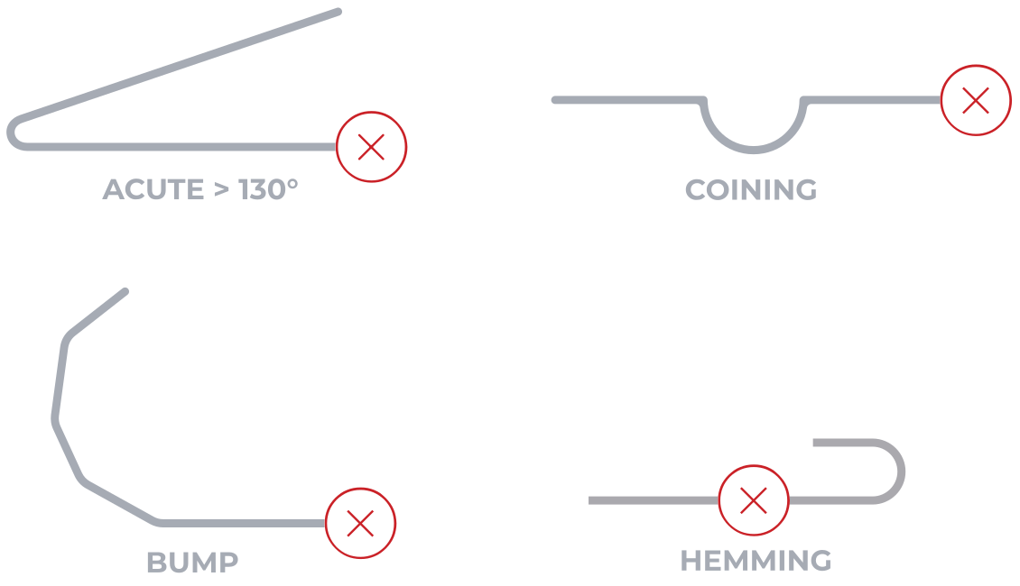
- No acute angles greater than 130°
- No obtuse angles less than 5°
- No curl, bump, or roll forming
- No coining or hemming
- No joggle bends in polycarbonate
What to expect with bent parts
All bent parts:
- Bend-to-edge tolerance: +/- 0.015″ (each additional bend adds at least 0.015″)
- Some bulging at the ends of bends is expected
- Witness marks from the bending process will be visible, these can become deeper and more noticeable depending on the material
- We don’t offer special protection for cosmetic parts at this time
Sheet metal bend angle tolerance:
- Bends up to 24″: +/- 1°
- Bends longer than 24″: +/- 2°
Polycarbonate bend angle tolerance:
- Bends up to 24″: +/- 5°
- Bends longer than 24″: +/- 7°
Polycarbonate-specific considerations:
- Adjacent flanges bent in the same direction need clearance.
- Polycarbonate is over-bent to achieve the desired angle, so we recommend 1:1 clearance to material thickness
- Minor surface edge cracks may appear depending on material thickness and bend angle
- Noticeable cracks will appear in stressed areas if adequate bend relief is not provided
Flange requirements
Minimum flange length depends on material and thickness — check the specs on your chosen material in the Material Catalog.
For U-channel and C-channel bends:
- Sheet metal: base must be at least 2x the flange length (2:1 ratio)
- Polycarbonate: base must be at least 3x the flange length (3:1 ratio)
Learn more about channel bend exceptions for thin sheet metal
Bend relief
Bend relief notches reduce stress on inner radii and prevent corner tearing or bulging. This is critical for polycarbonate, which cracks without adequate relief.
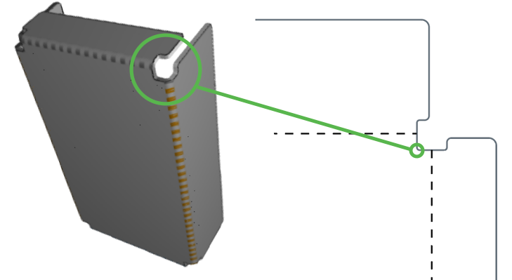
Learn more about bend relief requirements
Window and joggle bends
Window bends are allowed up to 90° for sheet metal and polycarbonate. More acute angles need review by our team.
Joggle bends are allowed up to 90° for sheet metal only. Min and max joggle flange values are on each material’s spec chart.
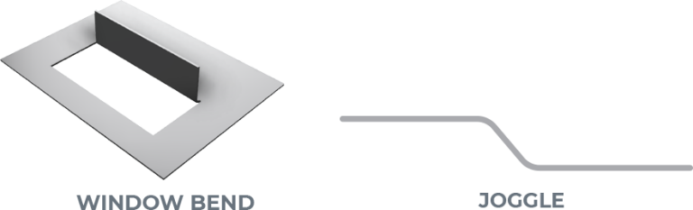
Window bend requirements
Joggle bend requirements
Odd flange shapes
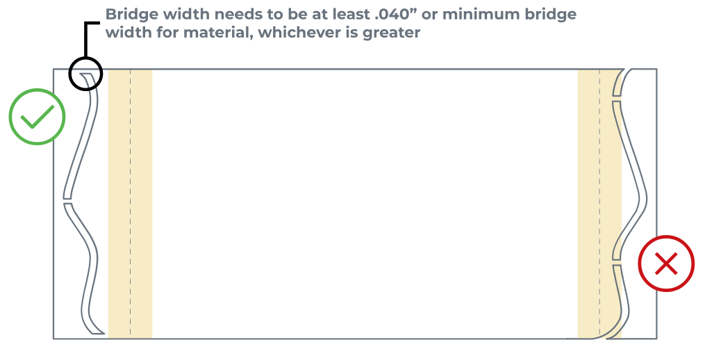
We can bend irregular flange shapes, but we need a flat surface parallel to the bend. Add break-off tabs to create a straight reference edge, then remove them after you receive your part.
See our complete guide on setting up break-off tabs
Our process: air bending
We form sheet metal and plastic with air bending, where the punch presses the material into a V-die without bottoming out. This affects bend radii and is especially important to understand for polycarbonate.
Die lines and feature distortion
Die lines are witness marks left where the tooling makes contact with your part during forming. Cut features that fall within die lines or the bend area will distort as the material stretches.

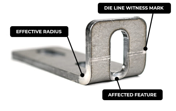
Learn how to avoid feature distortion in our Bending Deformation Guidelines
Common issues to avoid
Combined lines: Bends on a common axis must be joined. If they’re separate, each will be treated as an individual bend.
Intersecting bends: We can’t bend intersecting lines that don’t have separate flanges.
Incomplete bends: A bend must extend all the way across the area being bent. We can’t form partial bends.
Insufficient contact: Flanges need to meet the minimum flange length for at least ~50–60% of the bend’s length on both sides to provide enough press brake support. Thicker materials (.187″–.250″) need more contact.
Insufficient or missing bend relief: Certain designs require bend relief to avoid damage to the part. Without proper relief, a part cannot be bent accurately. This is critical for polycarbonate parts since the material is prone to cracking.
Additional bending resources
If you’re designing parts for powder coating, these resources may help:
- Processing min/max part sizes
- Material min/max part sizes
- Bending Deformation guidelines
- Bending Calculator
Pre-flight checklist
- File is in a format that we accept (2D: .dxf, .dwg, .ai, .eps; 3D: .step or .stp)
- All holes and cutouts are at least 50% material thickness for laser cut parts
- All holes and cutouts are no less than 0.070” for most waterjet cut parts
- All holes and cutouts are no less than 0.125” for all CNC routed parts
- File is built at a 1:1 scale, preferably in inch or mm units
- 2D files: all objects on the same layer, text converted to outlines, no open contours, all shapes united or merged, floating interiors bridged or stencilized
- 3D files: single solid sheet metal body, uniform thickness with a face at every edge, modeled at stock thickness with matching bend specs
- All stray points, duplicate lines, empty objects and text areas have been removed