


Design guidelines for countersunk parts
Following a few basic design guidelines will help ensure your parts are countersunk properly and pass SendCutSend review.
CAD setup & hole requirements
Draw only the minor hole in your CAD file
Do not include the major diameter; the countersink is machined to the correct size automatically.
Holes under 4″ are automatically resized
You are responsible for ensuring adequate edge clearance and spacing between features after resize.
Countersink direction matters
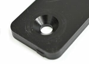
Countersinks can be applied from the top or bottom face. Use the 3D preview in the app to verify orientation before ordering.

Countersink sizing & geometry
| Major diameter | Should match fastener head diameter (~50% larger than minor hole). Do not include in your file |
| Minor diameter | Defined by your CAD file, must match intended fastener size |
| Max countersink depth | Should not exceed 60% of material thickness |
| Countersink angle: 82° | Standard for imperial/SAE hardware |
| Countersink angle: 90° | Standard for metric hardware |
| Contact requirement | Aim for ≥ 50% contact between hardware and countersink |
| Accuracy | ±0.015″ |
Countersink size reference charts
82° (Common for Imperial/SAE bolts) Major/Minor/Depth Chart
| Standard Flat Head Bolt | Major | Minor | Depth |
|---|---|---|---|
| 4-40 | 0.255” (6.48mm) | 0.130” (3.18mm) | .072″ (1.83mm) |
| 6-32 | 0.307” (7.80mm) | 0.164” (4.04mm) | .082″ (2.08mm) |
| 8-32 | 0.359” (9.12mm) | 0.193” (4.78mm) | .095″ (2.41mm) |
| 10-24 | 0.411” (10.44mm) | 0.199” (4.93mm) | .122″ (3.10mm) |
| 10-32 | 0.411” (10.44mm) | 0.199” (4.93mm) | .122″ (3.10mm) |
| 1/4-20 | 0.531” (13.49mm) | 0.255” (6.35mm) | .159″ (4.04mm) |
| 1/4-28 | 0.531” (13.49mm) | 0.255” (6.35mm) | .159″ (4.04mm) |
| 5/16-18 | 0.656” (16.66mm) | 0.318” (8.08mm) | .194″ (4.93mm) |
| 5/16-24 | 0.656” (16.66mm) | 0.318” (8.08mm) | .194″ (4.93mm) |
90° (Common for Metric bolts) Major/Minor/Depth Chart
| Metric Flat Head Bolt | Major | Minor | Depth |
|---|---|---|---|
| M2 x 0.4mm | 4mm (0.157”) | 2.39mm (0.099”) | .074mm (.029″) |
| M2.5 x 0.45mm | 5mm (0.197”) | 2.49mm (0.103”) | 1.19mm (.047″) |
| M3 x 0.5mm | 6mm (0.236”) | 3.18mm (0.130”) | 1.35mm (.053″) |
| M4 x 0.7mm | 8mm (0.315”) | 4.04mm (0.164”) | 1.93mm (.076″) |
| M5 x 0.8mm | 10mm (0.394”) | 5.00mm (0.202”) | 2.44mm (.096″) |
| M6 x 1mm | 12mm (0.472”) | 6.35mm (0.255”) | 2.77mm (.109″) |
| M8 x 1.25mm | 16mm (0.630”) | 8.00mm (0.320”) | 3.94mm (.155″) |
More details are available from our preferred vendor, McMaster
Spacing & structural considerations
Avoid placing countersinks too close to edges, other holes, or bend lines.
Deep countersinks require additional spacing between features and thicker material to maintain strength.
Multiple countersinks placed close together risk material deformation or part failure under load.

What to expect with countersunk parts
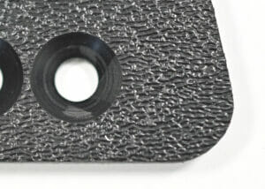
Surface condition: Parts may have oil or lubricant residue from the countersinking process. Light cleaning may be required.
Edge condition: Some sharp edges or burrs may remain after machining. Minor deburring may be needed.
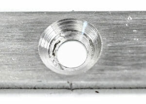
Finish quality: Countersinks are functional features, not cosmetic. Tooling marks or light scoring may be visible.
Powder coating impact: Adds .002″–.005″ per side. Hole sizes are adjusted, but fit may still be tight on countersunk features.
Additional Countersinking Resources
If you’re designing parts for countersinking, these resources may help:
Pre-flight checklist
- File is in a format that we accept (2D: .dxf, .dwg, .ai, .eps; 3D: .step or .stp)
- All holes and cutouts are at least 50% material thickness for laser cut parts
- All holes and cutouts are no less than 0.070” for most waterjet cut parts
- All holes and cutouts are no less than 0.125” for all CNC routed parts
- File is built at a 1:1 scale, preferably in inch or mm units
- 2D files: all objects on the same layer, text converted to outlines, no open contours, all shapes united or merged, floating interiors bridged or stencilized
- 3D files: single solid sheet metal body, uniform thickness with a face at every edge, modeled at stock thickness with matching bend specs
- All stray points, duplicate lines, empty objects and text areas have been removed